
System information


108 IBM and Cisco LAN Switching: Interoperability and Migration Guide
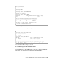
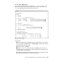
Figure 85. MPC status
In Figure 85 we can see:
1 The ATM address of the Cisco MPC default address with instance (00).
The ATM addresses are dynamically assigned instance by instance.
2 The MPS ATM address.
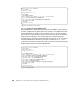
4.3.4 Verifying token-ring - Ethernet shortcut
Now we must verify that our MPS and MPCs are talking to each other and
that we can establish shortcut routing between the Ethernet and token-ring
segments. As shown in Figure 48 on page 77, we have two workstations, one
connected to the 8270 and one to Cisco 5500.
We generate IP traffic by pinging 40.40.40.20 from 110.10.10.34, and vice
versa pinging 110.10.10.34 from 40.40.40.20 simultaneously.
To verify what is happening, we will first take a look at the MPS Server in the
MSS, then the Cisco MPC client in the 5500 blade, and finally see what is
going on in the MSS client / MPC in the 8270 switch.
As already explained (Figure 75 on page 100), we tuned the configuration so
that having one ping per second will force a shortcut to be established. This
value would obviously not be chosen for a production environment. For a
production environment, we suggest you start with the default value of 10
frames in one second and tune it if needed.
As you will see, the test showed no problems, and the shortcut was easily
established between our clients.
mod9#show mpoa default-atm-addresses
interface ATM0:
MPOA Server: 39.0102030405060708090AA102.00D0BB6BA084.**
MPOA Client: 39.0102030405060708090AA102.00D0BB6BA085.**
note: ** is the MPS/MPC instance number in hex
mod9#show mpoa client
MPC Name: mod9-mpc-01, Interface: ATM0, State: Up
MPC actual operating address: 39.0102030405060708090AA102.00D0BB6BA085.00 1
Shortcut-Setup Count: 1, Shortcut-Setup Time: 1
Lane clients bound to MPC mod9-mpc-01: ATM0.11
Discovered MPS neighbours kp-alv vcd rxPkts txPkts
39.0102030405060708090AA102.000000000001.06 33 100 73 16 2