
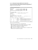
System information


Chapter 4. ATM LAN backbone interoperability and migration 107
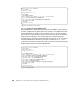
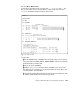
4.3.3.4 Verifying the Catalyst MPOA client configuration
We may now display the LANE and MPC configurations by means of the show
command. This provides useful information to verify the configuration and
diagnose errors we may have made:
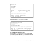
Figure 84. LEC joined ELAN S1Ethernet
In Figure 84 we can see the status of the 5500 module:
1 The default ATM addresses that would be used for the Local LANE
Client, LANE Server, LANE Bus and LANE Config Server.
2 Shows the LES for S1Ethernet on our MSS.
3 The router LEC on the MSS. The internal router has a connection to both
ELANs. This is the 110.10.10.1 gateway.
mod9#show lane default-atm-addresses
interface ATM0:
LANE Client: 39.0102030405060708090AA102.00D0BB6BA080.** 1
LANE Server: 39.0102030405060708090AA102.00D0BB6BA081.** 1
LANE Bus: 39.0102030405060708090AA102.00D0BB6BA082.** 1
LANE Config Server: 39.0102030405060708090AA102.00D0BB6BA083.00 1
note: ** is the subinterface number byte in hex
mod9#show lane client
LE Client ATM0.11 ELAN name: S1Ethernet Admin: up State: operational
Client ID: 3 LEC up for 15 minutes 23 seconds
ELAN ID: 2
Join Attempt: 23
Known LE Servers: 1
Last Fail Reason: Control VC being released
HW Address: 00d0.bb6b.a080 Type: Ethernet Max Frame Size: 1516 VL
ANID: 11
ATM Address: 39.0102030405060708090AA102.00D0BB6BA080.0B
VCD rxFrames txFrames Type ATM Address
0 0 0 configure 00.000000000000000000000000.000000000000.00
93 4 487 direct 39.0102030405060708090AA102.000000000001.03 2
94 479 0 distribute 39.0102030405060708090AA102.000000000001.03
95 0 748 send 39.0102030405060708090AA102.000000000001.03
96 108 0 forward 39.0102030405060708090AA102.000000000001.03
97 340 344 data 39.0102030405060708090AA102.000000000001.05 3