
System information


92 IBM and Cisco LAN Switching: Interoperability and Migration Guide
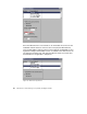
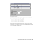
Figure 64. Configuring MPS ESI address and supported protocol
Since the MPS function is now turned on, we will enable the services for the
individual network interfaces. First we do it on the physical ATM interface
using our ESI address with the selector value of 06. We enable MPS for IP. In
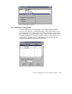
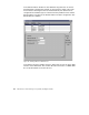
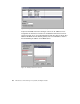
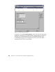
Figure 65 and Figure 66 the MPS services is enabled on the LEC interface for
our Ethernet and token-ring, and again the MPS for IP but not for IPX. Now
the MSS Server configuration is completed.
Figure 65. MPS token-ring interface