Quick Start Guide Cisco 7200 VXR Routers 1 Documentation and Resources 2 Prepare for Installation 3 Rack-Mount the Router 4 Connect the Router to the Network 5 Start and Configure the Router 6 After Installation 7 Cisco Product Security Overview 8 Obtaining Technical Assistance
1 Documentation and Resources This section contains information to help you prepare for installing the Cisco 7200 VXR router. It contains a list of online documentation and resources. Document Revision History The document revision history is in Table 1. Table 1 Document Revision History Document Version Date Notes OL-5012-05 May, 2006 This version of the document adds NPE-G2 information.
You can access the Cisco website at this URL: http://www.cisco.com You can access international Cisco websites at this URL: http://www.cisco.com/public/countries_languages.shtml Product Documentation DVD The Product Documentation DVD is a comprehensive library of technical product documentation on a portable medium. The DVD enables you to access multiple versions of installation, configuration, and command guides for Cisco hardware and software products.
To see security advisories, security notices, and security responses as they are updated in real time, you can subscribe to the Product Security Incident Response Team Really Simple Syndication (PSIRT RSS) feed. Information about how to subscribe to the PSIRT RSS feed is found at this URL: http://www.cisco.com/en/US/products/products_psirt_rss_feed.html Reporting Security Problems in Cisco Products Cisco is committed to delivering secure products.
• iQ Magazine is the quarterly publication from Cisco Systems designed to help growing companies learn how they can use technology to increase revenue, streamline their business, and expand services. The publication identifies the challenges facing these companies and the technologies to help solve them, using real-world case studies and business strategies to help readers make sound technology investment decisions. You can access iQ Magazine at this URL: http://www.cisco.
2 Prepare for Installation Warning Only trained and qualified personnel should install, replace, or service this equipment. Statement 1030 Warning Read the installation instructions before you connect the system to its power source. Statement 10 Warning This unit is intended for installation in restricted access areas.
Part Part • Port adapter documentation for configuring the interfaces • AC power cable-retention clip • T1 channel service unit/data service unit (CSU/DSU) that converts the High-Level Data Link Control (HDLC) synchronous serial data stream into a T1 data stream with the correct framing and ones density to connect a serial port to a T1 network. (Some telephone systems require a minimum number of 1 bits per time unit in a data stream, called ones density.
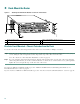
Figure 1 Installing a CompactFlash Disk 1 2 ORK PR OCESSING ENGINE - G1 ORK PR OCESSING ENGINE - G1 CT FLA SH C O M PA ORK PR OCESSING ENGINE - G1 C O M PA CT FLA SH CT FLA SH 66776 C O M PA 3 1 Inserting the CompactFlash Disk 2 Releasing the CompactFlash Disk 3 Removing the CompactFlash Disk Step 1 Turn the CompactFlash Disk so that the label is facing down. It is keyed and cannot be inserted incorrectly. Step 2 Slide the CompactFlash Disk into the CompactFlash Disk slot.
Figure 3 Inserting an SFP Module into the NPE-G2 Gigabit Ethernet Port 0/1 LINK ACTV 1 EN GIGABI T ETHE RNET 0 LINK ACTV /1 GIGABI T ETHE RNET 0 LINK ACTV TX RX RJ45 /2 EN EN 149065 RJ45 2 SFP port 0/1 1 2 SFP module Use the following procedure to install an SFP module in the NPE-G2: Step 1 Attach an ESD-preventive wrist strap between you and an unpainted chassis surface.
3 Rack-Mount the Router Figure 4 Attaching the Rack-Mount Brackets to the Front of the Chassis EN 5 6 3 2 1 4/1 0 AB IN-R LE D 6 Mb ING ps TOKEN RING 5 4 RJ4 LI NK MII 0 2 TX RX 4 TX 3 RX TX RX 2 RX 1 M II R ES ET PO O WE K R 1O C PU EN FE AB L FE E LIN K 0 FE SL O T 0 EJE C T SL O T PC M C IA EN AB LE D 1 53498 3 FAST ETHERNET INPUT/OUTPUT CONTROLLER 1 Cisco 7200 Series TX EN TX 1 0 CD LB RC RD TC TD CD LB RC RD TC TD CD LB RC RD TC TD C
Figure 5 Attaching the Rack-Mount Brackets to the Front of the Chassis—Chassis Recessed 6 3 2 1 0 EN AB LE D IN-R 4/1 6 Mb ING ps TOKEN RING 5 FAST ETHERNET 5 4 RJ4 0 LI MII NK D EN 2 TX RX 4 TX 3 RX TX RX 2 M II R ES ET PO O WE K R 1O C PU EN FE AB L FE E LIN K 0 SL O T EJE C T PC M C IA EN AB LE D 0 FE SL O T RX 1 FAST ETHERNET INPUT/OUTPUT CONTROLLER 1 Cisco 7200 Series TX EN TX 1 0 CD LB RC RD TC TD CD LB RC RD TC TD ETHERNET-10BFL RX 3 2 CD
Installing the Rear Cable-Management Brackets with an NPE-G1 or NPE-G2 Installed—Router Front-Mounted H6423 Figure 6 GIGABIT ETHERNET 0/1 GIGABIT ETHERNET 0/1 LINK GIGABIT ETHERNET 0/1 LINK NETWORK PROCESSING ENGINE - G1 LINK CPU RESET EN RX GBIC TX RJ45 EN RX GBIC TX RJ45 SLOT ACTIVE EN RX GBIC TX C O M PA C T F L A S H POWER OK CONSOLE AUX 84399 RJ45 NPE-G1 and NPE-G2 Rear Cable-Management Brackets on a Front-Mounted Router If you have an NPE-G1 or NPE-G2 installed, install cab
Figure 7 Attaching the Rack-Mount Brackets to the Rear of the Chassis—Front Protrudes from the Rack 6 3 2 1 0 EN AB LE D IN-R 4/1 6 Mb ING ps TOKEN RING 5 FAST ETHERNET 5 4 RJ4 0 LI MII NK D EN 1 2 TX RX 4 TX RX 3 TX 2 ER ET ES K W R PO PU O 1O C EN FE AB L FE E LIN K 0 T T EC O EJ SL EN PC M AB C IA LE D 0 FE M II T O SL RX TX FAST ETHERNET INPUT/OUTPUT CONTROLLER 1 Cisco 7200 Series RX 1 RX TX EN ETHERNET-10BFL 0 CD LB RC RD TC TD C
Figure 8 Attaching the Rack-Mount Brackets to the Rear of the Chassis—Front Recessed 6 3 2 1 0 EN AB LE D IN-R 4/1 6 Mb ING ps TOKEN RING 5 FAST ETHERNET 4 RJ4 5 MII 0 1 2 TX RX 4 TX RX 3 TX RX FAST ETHERNET INPUT/OUTPUT CONTROLLER ES ET W ER R PO K PU 57003 O C 1O EN FE AB L FE E LIN K 0 SL O T T EJ EC EN PC M C IA AB LE D 0 FE M II T SL O 2 TX RX 1 1 Cisco 7200 Series 1 LI NK D LE AB EN TX EN ETHERNET-10BFL 0 CD LB RC RD TC TD CD LB RC
Installing the Rear Cable-Management Brackets with the NPE-G1 or NPE-G2—Router Rear-Mounted 84400 Figure 9 EN GIGABIT ETHERNET 0/1 GIGABIT ETHERNET 0/1 LINK GIGABIT ETHERNET 0/1 LINK NETWORK PROCESSING ENGINE - G1 LINK CPU RESET RJ45 EN RX GBIC TX RJ45 EN RX GBIC TX RJ45 SLOT ACTIVE EN RX GBIC TX POWER ON C O M PA C T F L A S H CONSOLE AUX NPE-G1 or NPE-G2 Rear Cable-Management Brackets on a Rear-Mounted Router If you have an NPE-G1 or NPE-G2 installed, install cable-management b
NPE-G1 or NPE-G2 Optical Cable-Management Bracket Step 1 Loosen the left and right captive installation screws. Step 2 Hold the cable-management bracket so that it is positioned as shown in Figure 10. Step 3 Place the left end of the cable-management bracket over the screw. Step 4 Rotate the cable-management bracket down, until it slides behind the right captive installation screw. Step 5 Tighten both captive installation screws.
Figure 12 Installing the Chassis Ground Connection 1 3 57006 2 4 NETWORK PROCESSING ENGINE-300 1 Chassis ground connector 3 Screws 2 Grounding lug 4 Wire Install the Chassis Ground Note The grounding lug and Phillips screws are not available from Cisco Systems. Get the grounding lug from an electrical-connector vendor and the screws from a hardware vendor. See “Tools and Parts” section on page 6 for the parts needed.
4 Connect the Router to the Network Figure 13 Connecting the Console and Auxiliary Port Cables 2 ET FAST ETHERNET INPUT/OUTPUT CONTROLLER ES II 45 57007 C 1O O PW K R R L J4 IN 5 K M E II N R E J4 N 5 T 0 T EC O EJ SL PC M C IA EN AB LE D R J- PU R M FE SL O T 1 1 4 3 1 Auxiliary port-DTE-mode; EIA/TIA-232, DTE-DB-25 connector (for modem, CSU/DSU, and so on.
Depending on the I/O controller installed in your Cisco 7200 VXR router, you may have a Gigabit Ethernet port, RJ-45 ports, or no Ethernet port. The following table provides information about the types of ports on different I/O controller models. Table 2 I/O Controller Port Information Product Number Description C7200-I/O-GE+E 1 Gigabit Ethernet and 1 Ethernet port; equipped with a GBIC receptacle for 1000 megabits per second (Mbps) operation and an RJ-45 receptacle for 10-Mbps operation.
SFP and GBIC Interface Cables Installation For more information on cables, specifications, or product numbers, see the Cisco 7200 VXR Installation and Configuration Guide or the Network Processing Engine or Network Services Engine Installation and Configuration. Note All SFPs have LC type connectors. All GBIC ports have SC-type connectors. After the GBIC or SFP is installed in the Gigabit Ethernet port, you must attach the optical fiber cables to the SFP or GBIC.
Note Ensure that you connect the TX and RX ports on one end of the patch cord to the RX and TX ports (respectively) on the other end. Connect TX to RX and RX to TX. Port Adapter Cable Connections The instructions for connecting the cables for each port adapter installed in the Cisco 7200 VXR routers are in the respective online note for each port adapter. The documents are available on the Documentation DVD and on Cisco.com.
5 Start and Configure the Router Power Cable Connections Caution This unit might have more than one power cord. To reduce the risk of electric shock, disconnect the two power supply cords before servicing the unit. Statement 83 Warning The AC power supply has double pole/neutral fusing. Statement 188 Connect AC-Input Power When powering off the router, wait a minimum of 30 seconds before powering it on again.
Step 6 Plug the AC power supply cable into the AC power source. Repeat Step 1 through Step 6 for the second power supply (if present). Connect DC-Input Power Note The color coding of the DC-input power supply leads depends on the color coding of the DC power source at your site. Typically, green or green/yellow is used for ground. Make certain the lead color coding you choose for the DC-input power supply matches lead color coding used at the DC power source.
Note Step 6 Make sure the entire stripped end of each lead is inserted all the way into its receptacle. If any exposed wire at the stripped end of a lead is visible after inserting the lead into its receptacle, remove the lead from the receptacle, use the wire stripper to cut the stripped end of the lead, and repeat Step 3 through Step 5. Use a cable tie to secure the leads to the power supply.
Start the System and Perform a Basic Configuration Step 1 Check that all hardware parts and cables are securely attached to the chassis. Step 2 Check that a CompactFlash Disk, Flash Disk, or PC Card or Flash memory card is installed. Step 3 Check that the console terminal is turned on.
At any point you may enter a questions mark ‘?’ for help. Use ctrl-c to abort configuration dialog at any prompt. Default settings are in square brackets ‘[]’. continue with configuration dialog? [yes]: Step 1 Enter yes or press Return to enter the initial configuration dialog. You have the option of proceeding with the setup facility to configure the interfaces, or exiting from setup and using configuration commands to configure global (system-wide) and interface-specific parameters.
cisco Systems, Inc. 170 West Tasman Drive San Jose, California 95134-1706 Cisco Internetwork Operating System Software IOS (tm) 7200 Software (C7200-JS-M), Released Version 12.0(19980705:021501)Copyright(c) 1986-1998 by cisco Systems, Inc. Compiled Thu 15-Oct-98 02:20 by xxxxx Image text-base: 0x600088C4, data-base: 0x60FA6000 cisco 7206VXR (NPE300) processor with 61440K/20480K bytes of memory. R7000 CPU at 262Mhz, Implementation 39, Rev 1.0, 256KB L2, 2048KB L3 Cache Six slot VXR midplane, Version 2.
Enter enable secret: barney The enable password is used when there is no enable secret password and when using older software and some boot images. Enter enable password: betty Enter virtual terminal password: fred Step 6 The Simple Network Management Protocol (SNMP) is the most widely supported open standard for network management. It provides a means to access and set configuration and run-time parameters of routers and communication servers.
Configure IGRP routing? [yes]: Your IGRP autonomous system number [1]: 15 Configure RIP routing? [no]: Configure CLNS? [no]: n Configure bridging? [no]: Configure IPX? [no]: yes Configure XNS? [no]: Configure Apollo? [no]: Step 10 Save your settings to NVRAM. (See the “Save the Running Configuration to NVRAM” section on page 34.) Save the configuration settings that you created in the router using the configuration mode and the setup facility.
Configure the Interface Transmission and Speed Modes for the NPE-G1 or NPE-G2 Step 1 After changing the media type, configure the speed and transmission modes to appropriately match the new interface characteristics. Changing the speed and duplex of an NPE-G1 Gigabit Ethernet interface is done using the speed and duplex interface commands. Note These commands are only applicable when using the RJ-45 media.
Reset the Interface on the NPE-G1 or NPE-G2 Should you have a problem with your NPE-G1 or NPE-G2 interface and wish to try and reset it, use the command: clear interface GigabitEthernet 0/X (where X is 1, 2, or 3) Clear Counters on the NPE-G1 or NPE-G2 NPE-G1 or NPE-G2 interface counters may be cleared (reset) by using the command: clear counters GigabitEthernet 0/X (where X is 1, 2, or 3) This will not reset the interface.
Configure Fast Ethernet Interfaces In the following example, a Fast Ethernet interface in slot 2 is configured for a Fast Ethernet LAN using IP.
Step 3 If you are using AppleTalk on the interface, enter yes. Enter yes to configure for extended AppleTalk networks, and then enter the cable range number. Enter the zone name and any other additional zones that are associated with your local zone: Configure AppleTalk on this interface? [no]: yes Extended AppleTalk network? [no]: yes AppleTalk starting cable range [0]: Step 4 Save your settings to NVRAM. (See the “Save the Running Configuration to NVRAM” section on page 34.
enable password betty line vty 0 4 password fred snmp-server community public ip routing no vines routing ipx routing appletalk routing no apollo routing no decnet routing no xns routing no clns routing no bridge 1 ! Turn off IPX to prevent network conflicts. interface ATM1/0 ip address 1.1.1.10 255.0.0.1 appletalk cable-range 0-0 0.0 appletalk discovery ! interface FastEthernet2/0 media-type 100BaseX half-duplex ip address 1.1.1.20 255.0.0.2 appletalk cable-range 0-0 0.
Check the Running Configuration Settings To check the value of the settings you have entered, enter the show running-config command at the Router# prompt: Router# show running-config To review changes you make to the configuration, use the EXEC mode show startup-config command to display the information stored in NVRAM.
6 After Installation This section contains hardware replacement instructions. The PC card or Flash memory card, CompactFlash Disk, Flash Disk, GBIC, SFP, and port adapters support online insertion and removal (OIR).
Note If you have difficulty installing a processing engine or I/O controller in the lowest slot of a Cisco 7200 VXR router that is rack-mounted, remove the port adapters, processing engine and I/O controller from the chassis and reinstall them. Install the processing engine and I/O controller in the lowest slots first, then populate the slots above them, in a bottom-to-top order. Step 5 Grasp the handle and pull the NPE or NSE from the chassis.
Note If you have difficulty installing a processing engine or I/O controller in the lowest slot of a Cisco 7200 VXR router that is rack-mounted, remove the port adapters, processing engine and I/O controller from the chassis and reinstall them. Install the processing engine and I/O controller in the lowest slots first, then populate the slots above them, in a bottom-to-top order. Step 5 Insert the I/O controller and tighten the captive installation screws. Step 6 Connect any I/O controller cables.
To replace the CompactFlash Disk in the NPE-G1, see the “Prepare for Installation” section on page 6. Also see Using the Flash Disk at http://www.cisco.com/en/US/docs/routers/7200/install_and_upgrade/flash_disk_install_config/6452fd.html, and Memory Replacement Instructions for the Network Processing Engine or Network Services Engine and I/O Controller at http://www.cisco.com/en/US/docs/routers/7200/install_and_upgrade/npe-nse_memory_install/memory.html.
Replace the SFP–NPE-G2 Figure 22 Inserting an SFP Module into the NPE-G2 Gigabit Ethernet Port 0/1 LINK ACTV 1 EN GIGABI T ETHE RNET 0 LINK ACTV /1 GIGABI T ETHE RNET 0 LINK ACTV TX RX RJ45 /2 EN EN 149065 RJ45 2 1 SFP port 0/1 2 SFP module Use the following procedure to install an SFP module in the NPE-G2: Step 1 Attach an ESD-preventive wrist strap between you and an unpainted chassis surface.
To connect a Cisco USB Flash memory module or the Aladdin USB eToken Pro key to the NPE-G2 USB port, simply insert the module into the port as shown in Figure 23. The Flash memory module can be inserted in only one way, and can be inserted or removed regardless of whether the router is powered up or not. Do not remove a USB Flash memory module when a read or write operation to the USB Flash memory module is in progress. The router might reload, or the USB Flash memory module card can be damaged.
Step 3 With the port adapter halfway out of the slot, disconnect all cables from the port adapter. After disconnecting the cables, pull the port adapter from its chassis slot. Step 4 To insert the port adapter, carefully align the port adapter carrier between the upper and the lower edges of the port adapter slot guide (4) and slide the new port adapter halfway into the port adapter slot (3). Step 5 Connect all required cables to the port adapter.
Figure 26 Removing the Port Adapter Jacket Card 3 2 1 0 6 TOKEN RING 5 FAST ETHERNET 4 RJ4 5 MII 0 LIN K D LE AB EN 2 TX RX TX RX 0 3 TX TX RX RX 2 4 138888 1 Cisco 7200 Series VXR 1 TX EN ETHERNET-10BFL 0 CD LB RC RD TC TD CD LB RC RD TC TD CD LB RC RD TC TD CD LB RC RD TC TD EN FAST SERIAL RX 3 3 2 2 1 0 LINK 1 0 3 EN AB LE D ETHERNET 10BT PW R EN AB LE D PORT ADAPTER JACKET CARD Note If you have difficulty removing the Port Ada
Replace the Power Supply Replacing the Power Supply 2 4 3 1 2 5 4 3 1 5 1 Power switch 4 Captive installation screws 2 PWR OK LED 5 Handle 3 AC/DC power input connection 57038 Figure 27 Caution Do not mix power supplies in Cisco 7200 VXR routers. In dual power supply configurations, both power supplies must be of the same type (two AC-input power supplies or two DC-input power supplies).
7 Cisco Product Security Overview Cisco provides a free online Security Vulnerability Policy portal at this URL: http://www.cisco.com/en/US/products/products_security_vulnerability_policy.html From this site, you can perform these tasks: • Report security vulnerabilities in Cisco products. • Obtain assistance with security incidents that involve Cisco products. • Register to receive security information from Cisco.
8 Obtaining Technical Assistance Cisco Technical Support provides 24-hour-a-day award-winning technical assistance. The Cisco Technical Support & Documentation website on Cisco.com features extensive online support resources. In addition, if you have a valid Cisco service contract, Cisco Technical Assistance Center (TAC) engineers provide telephone support. If you do not have a valid Cisco service contract, contact your reseller.
Definitions of Service Request Severity To ensure that all service requests are reported in a standard format, Cisco has established severity definitions. Severity 1 (S1)—An existing network is down, or there is a critical impact to your business operations. You and Cisco will commit all necessary resources around the clock to resolve the situation.
Corporate Headquarters Cisco Systems, Inc. 170 West Tasman Drive San Jose, CA 95134-1706 USA www.cisco.com Tel: 408 526-4000 800 553-NETS (6387) Fax: 408 526-4100 European Headquarters Cisco Systems International BV Haarlerbergpark Haarlerbergweg 13-19 1101 CH Amsterdam The Netherlands www-europe.cisco.com Tel: 31 0 20 357 1000 Fax: 31 0 20 357 1100 Americas Headquarters Cisco Systems, Inc. 170 West Tasman Drive San Jose, CA 95134-1706 USA www.cisco.