
Specifications


1-66 Cisco 7000 Hardware Installation and Maintenance
Functional Overview
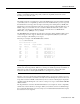
The following example shows only the Temperature Parameters section of the table. In this example,
the measured value at the inlet sensor is 41°C, which falls within the warning range (39°C through
46°C) and therefore is displayed in the Warning column.
Temperature Parameters:
SENSE WARNING NORMAL WARNING CRITICAL SHUTDOWN
------|-------------|------------|-------------|--------------|------------
Inlet 10 39 41(C) 46 64
Air-flow 10 40(C) 60 70 88
For complete command descriptions and instructions, refer to the related software command
reference documentation on UniverCD or in the printed manuals.
In addition to the environmental displays, the front-panel and power-supply LEDs indicate the status
of the system power. When a power supply is installed and supplying power to the system, the front
panel power LED is on for the indicated bay (upper power bay or lower power bay), and the AC
power LED on the power supply is on. If a power supply fails, the front-panel LED for the power
supply that fails goes off, and the yellow DC Fail LED on the power supply (shown in Figure 1-6)
goes on.