
Specifications

Product Overview 1-45
Physical Description
stations (SASs), dual attachment stations (DASs), dual homing, and optical bypass. The FIP
complies with ANSI X3.1 and ISO 9314 FDDI standards. The default FIP microcode resides on a
ROM in socket U23.
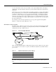
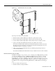
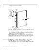
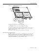
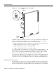
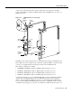
Figure 1-17 FDDI I Interface Processor (FIP)
Each FIP provides a single network interface for both multimode and single-mode FDDI networks.
The two FIP connectors are available in any combination of multimode (MIC) or single-mode (FC)
connectors for matching multimode and single-mode fiber in the same FDDI network.
The following combinations are available:
• CX-FIP-MM—FDDI PHY-A multimode, PHY-B multimode interface processor
• CX-FIP-MS—FDDI PHY-A multimode, PHY-B single-mode interface processor
• CX-FIP-SM—FDDI PHY-A single-mode, PHY-B multimode interface processor
• CX-FIP-SS—FDDI PHY-A single-mode, PHY-B single-mode interface processor
As with the other interface processors, the Enabled LED lights to indicate that the FIP is enabled for
operation. Below the Enabled LED, a bank of six LEDs indicate the state of the two physical
sublayer connections (PHY B and PHYA). The upper row of three LEDs indicates PHY B; the
lower row indicates PHY A. (The PHY B interface is located above the PHYA interface on the face
of the FIP, as shown in Figure 1-17.) The state of each B/A pair of LEDs indicates the status of one
U23
Optical
bypass port
Multimode
ports
ENABLED
ENABLED
DH SAS DAS
A
B
PHY B
PHY A
H1730
U23
ENABLED
Single-mode
ports
TX
RX
Socket
with ROM
Captive
installation
screw
Captive
installation
screw
LEDs
Multimode
port