
Installation guide

Chapter 3 Switch Installation
Preparing for Installation
3-8
Catalyst 3750 Switch Hardware Installation Guide
78-15136-02
–
Six Phillips flat-head screws for attaching the brackets to the switch
(Catalyst 3750-24TS, 3750G-24T, and 3750-48TS switches)
–
Four Phillips machine screws for attaching the brackets to a rack
–
One cable guide and one black Phillips machine screw for attaching the
cable guide to one of the mounting brackets
–
One redundant power system (RPS) connector cover (for wall mounting)
–
Two Phillips pan-head screws (for attaching the RPS cover)
–
Four Phillips truss-head screws (for wall-mounting brackets)
–
StackWise cable: 0.5-meter, 1-meter, or 3-meter cable.
Note If you don’t specify the length of the StackWise cable, the 0.5-meter cable
is supplied by default.
Verifying Switch Operation
Before installing the switch in a rack, on a wall, or on a table or shelf, you should
power the switch and verify that the switch passes POST. These sections describe
the steps required to connect a PC to the switch console port, and to power on the
switch and observe POST:
• Connecting a PC or Terminal to the Console Port, page 3-8
• Powering On the Switch and Running POST, page 3-10
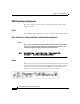
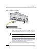
Connecting a PC or Terminal to the Console Port
To connect a PC to the console port, use the supplied RJ-45-to-DB-9 adapter
cable. To connect the switch console port to a terminal, you need to provide a
RJ-45-to-DB-25 female DTE adapter. You can order a kit (part number
ACS-DSBUASYN=) containing that adapter from Cisco. For console port and
adapter pinout information, see the “Cable and Adapter Specifications” section on
page B-6.
The terminal-emulation software—frequently a PC application such as
Hyperterminal or Procomm Plus—makes communication between the switch and
your PC or terminal possible.