
Installation guide

2-13
Catalyst 3560 Switch Hardware Installation Guide
OL-6337-03
Chapter 2 Switch Installation
Installing the Switch
Attaching the Brackets to the Switch for Wall Mounting
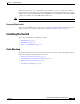
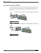
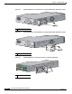
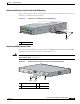
Figure 2-10 shows how to attach a 19-inch bracket to one side of the switch. Follow the same steps to
attach the second bracket to the opposite side.
Figure 2-10 Attaching the 19-inch Brackets for Wall Mounting
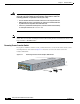
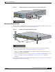
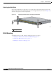
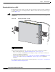
Attaching the RPS Connector Cover
If you are not using an RPS with your switch, use the two Phillips pan-head screws to attach the RPS
connector cover to the back of the switch, as shown in Figure 2-11.
Warning
If a redundant power system (RPS) is not connected to the switch, install an RPS connector cover on
the back of the switch.
Statement 265
Figure 2-11 Attaching the RPS Connector Cover on the Catalyst 3560 Switch
1 Cable guide screw
40
41
42
43
44
45
46
47
48
4
7
X
4
8
X
97925
Catalyst 3560
SERIES
P
o
E
-4
8
1
2
3
4
1
1 Phillips pan-head screws 3 RPS connector
2 RPS connector cover
97926
RATING
100-200V ~
5.0A-2.5A, 50-60 HZ
C
O
N
SO
LE
DC INPUTS FOR REMOTE
POWER SUPPLY
SPECIFIED IN MANUAL
+12v @7.5A -48 @7.8A
2
3
1