
Specifications


27-14
Catalyst 2950 and Catalyst 2955 Switch Software Configuration Guide
78-11380-07
Chapter 27 Configuring QoS
Auto-QoS Configuration Example
Auto-QoS Configuration Example
Note This example is applicable only if your switch is running the EI.
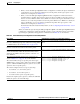
This section describes how you could implement auto-QoS in a network, as shown in Figure 27-3.
Figure 27-3 Auto-QoS Configuration Example Network
The intelligent wiring closets in Figure 27-3 are composed of Catalyst 2950 switches running the EI and
Catalyst 3550 switches. The object of this example is to prioritize the VoIP traffic over all other traffic.
To do so, enable auto-QoS on the switches at the edge of the QoS domains in the wiring closets.
Note You should not configure any standard-QoS commands before entering the auto-QoS commands. You
can fine-tune the QoS configuration, but we recommend that you do so only after the auto-QoS
configuration is completed.
Cisco router
Intelligent wiring closet
Catalyst 2950 and 3550
switches
Catalyst
3550-24-EMI
switch
Catalyst 2950 switch
at the edge of the
QoS domain
Catalyst 2950 switch
at the edge of the
QoS domain
Catalyst
3550-24-EMI
switch
Fast
Ethernet 0/1
Fast
Ethernet 0/1
Intelligent wiring closet
Catalyst 2950 and 3550
switches
To Internet
Catalyst 3550-12G switch
Gigabit Ethernet 0/5
Gigabit Ethernet 0/2
Gigabit
Ethernet
0/2
Gigabit
Ethernet
0/1
Trunk
link
Gigabit Ethernet 0/1
Trunk
link
Cisco IP phones
Fast Ethernet 0/7
Fast Ethernet 0/3
Fast Ethernet 0/7
Fast Ethernet 0/3
Fast Ethernet 0/5 Fast Ethernet 0/5
Cisco IP phones
Video server
172.20.10.16
86436
IP
IP
IP
IP
IP
IP