C H A P T E R 4 Configuring the Gigabit Ethernet Ports Warning Before you install, operate, or service the system, read the Site Preparation and Safety Guide . This guide contains important safety information you should know before working with the system. Statement 200 Warning Only trained and qualified personnel should be allowed to install, replace, or service this equipment.
Chapter 4 Configuring the Gigabit Ethernet Ports Installing, Removing, and Maintaining GBICs • GBIC Features, page 4-2 • Port Cabling Specifications, page 4-3 • GBIC Optical Power Characteristics, page 4-4 • GBIC Cabling Restrictions, page 4-5 • Installing GBICs, page 4-6 • Removing GBICs, page 4-9 • GBIC Maintenance Guidelines, page 4-10 • Patch Cord, page 4-10 GBIC Features Warning Because invisible laser radiation may be emitted from the aperture of the port when no cable is connected
Chapter 4 Configuring the Gigabit Ethernet Ports Installing, Removing, and Maintaining GBICs Table 4-1 Note Supported GBIC modules GBIC Type Model Number Fiber-optic 1000BASE-SX WS-G5484= Fiber-optic 1000BASE-LX/LH WS-G5486= Fiber-optic 1000BASE-ZX WS-G5487= Copper 1000BASE-TX GBIC WS-G5483= Coarse Wave Division Multiplexing (CWDM) fiber-optic 1000BASE-X GBIC CWDM-GBIC-1470= CWDM-GBIC-1490= CWDM-GBIC-1510= CWDM-GBIC-1530= CWDM-GBIC-1550= CWDM-GBIC-1570= CWDM-GBIC-1590= CWDM-GBIC-1610= Cisco
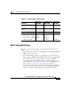
Chapter 4 Configuring the Gigabit Ethernet Ports Installing, Removing, and Maintaining GBICs Note For information about the Coarse Wave Division Multiplexing (CWDM), refer to the Cisco CWDM GBIC and CWDM SFP Installation Note. Table 4-2 GBIC Port Cabling Specifications GBIC Wavelength1 (nm) Fiber Type Core Size (microns) Modal Bandwidth (MHz/km) Maximum Cable Distance SX2 850 62.5 160 722 ft (220 m) 62.5 200 902 ft (275 m) 50.0 400 1640 ft (500 m) 50.0 500 1804 ft (550 m) 62.
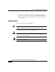
Chapter 4 Configuring the Gigabit Ethernet Ports Installing, Removing, and Maintaining GBICs Table 4-3 GBIC Optical Power Characteristics 1000BASE-SX (WS-G5484) 1000BASE-LX/LH 1000BASE-ZX (WS-G5486) (WS-G5487) Transmitter output power (min/max) 0/–9.5 dBm –3/–9.5 dBm 0/4.77 dBm Receiver maximum input power 0 dBm –3 dBm –3 dBm Receiver sensitivity –17 dBm –19 dBm –23 dBm 50/125 micron1 MMF 3.4 dBm 4.4 dBm – 62.5/125 micron MMF 3.2 dBm 6 dBm – 9/10 micron SMF 6.5 dBm 21.
Chapter 4 Configuring the Gigabit Ethernet Ports Installing, Removing, and Maintaining GBICs • You must insert a 5-dB inline optical attenuator between the single-mode fiber-optic network and the receiving port on the 1000BASE-ZX GBIC at each end of the link if the link is greater than 15.5 miles (25 km), but less than 31 miles (50 km). Installing GBICs This section describes how to install GBICs. Caution Unnecessary removal and insertion of a GBIC could lead to premature failure of the GBIC.
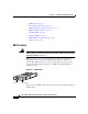
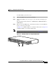
Chapter 4 Configuring the Gigabit Ethernet Ports Installing, Removing, and Maintaining GBICs To install a GBIC, perform these steps: Step 1 Remove the GBIC from its protective packaging. Step 2 Verify that the GBIC is the correct type for your network by checking the part number. The part number indicates whether it is 1000BASE-SX, 1000BASE-LX/LH, or 1000BASE-ZX. Step 3 Grip the sides of the GBIC with your thumb and forefinger; insert the GBIC into the slot on the front of the module.
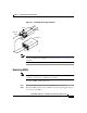
Chapter 4 Configuring the Gigabit Ethernet Ports Installing, Removing, and Maintaining GBICs Figure 4-3 Installing a GBIC on a Catalyst 2980G Switch 1 2 SLOT 2 3 4 5 6 7 8 9 10 11 12 13 14 15 17 18 19 20 19 20 21 2 10/100/100 22 23 24 0 ETHE RENE T 1 2 3 4 5 6 7 8 9 2 16 25 26 CATALY 27 28 11 12 13 14 15 30 31 18 21 22 23 33 34 35 36 37 38 39 40 41 42 43 44 48 45 24 SLOT25 26 3 27 28 29 31 46 47 48 CONSOLE 32 30 6 32 16
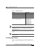
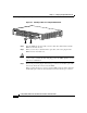
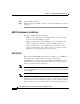
Chapter 4 Configuring the Gigabit Ethernet Ports Installing, Removing, and Maintaining GBICs Figure 4-4 Connecting the SC-Type Connector Keys Cable Light out of fiber Receptacle Key slots Note 17110 Tr an sm R itt ec er ei ve r Light into fiber If you are using the LX/LH GBIC with MMF, you need to install a patch cord between the GBIC and the MMF cable. See the “Patch Cord” section on page 4-10 for details.
Chapter 4 Configuring the Gigabit Ethernet Ports Installing, Removing, and Maintaining GBICs Step 3 Slide the GBIC out of the slot. Step 4 Install the plug into the GBIC optical bores and place the GBIC in its protective packaging. GBIC Maintenance Guidelines Follow these GBIC maintenance guidelines: • GBICs are static sensitive. To prevent ESD damage, follow your normal board and component handling procedures. • GBICs are dust sensitive.
Chapter 4 Configuring the Gigabit Ethernet Ports Installing, Removing, and Maintaining GBICs the output of the patch cord, the LX/LH GBIC is compliant with the IEEE 802.3z standard for 1000BASE-LX. For a detailed description of this problem, refer to Appendix C, “Differential Mode Delay.” Note Cisco Gigabit Ethernet products have been tested and evaluated to comply with the standards listed in Appendix A, “Specifications.” Equivalent cables should also meet these standards.
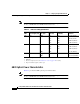
Chapter 4 Configuring the Gigabit Ethernet Ports Installing, Removing, and Maintaining GBICs Patch Cord Configuration Example Figure 4-5 shows a typical configuration using patch cords. Figure 4-5 Patch cord Patch Cord Configuration Building cable plant Patch cord Rx Tx Patch panel Patch panel Tx 1000BASE-LX/LH port Rx 13088 1000BASE-LX/LH port Link span greater than 984 ft (300 m) Patch Cord Installation Plug the end of the patch cord labeled “To equipment” into the GBIC (see Figure 4-6).
Chapter 4 Configuring the Gigabit Ethernet Ports Connecting To an SFP Module Connecting To an SFP Module This section describes how to connect to an SFP module. For instructions about how to install or remove an SFP module, refer to the Cisco Small Form-Factor Pluggable Modules Installation Notes (not orderable but is available on Cisco.com) and to the documentation that came with your SFP module. Table 4-4 lists the SFP modules supported by the Catalyst 2948G-GE-TX switch.
Chapter 4 Configuring the Gigabit Ethernet Ports Connecting To an SFP Module Table 4-5 Fiber-Optic SFP Module Port Cabling Specifications Core Size (micron) Modal Bandwidth (MHz/km) Cable Distance MMF 62.5 62.5 50.0 50.0 160 200 400 500 722 ft (220 m) 902 ft (275 m) 1640 ft (500 m) 1804 ft (550 m) MMF1 62.5 50.0 50.0 9/10 500 400 500 — 1804 ft (550 m) 1804 ft (550 m) 1804 ft (550 m) 6.2 mi (10 km) 9/10 — 43.
Chapter 4 Configuring the Gigabit Ethernet Ports Connecting To an SFP Module For the latest information about SFP modules supported by the switch, refer to the release notes. Caution Do not remove the rubber plugs from the ports on fiber-optic SFP modules or the rubber caps from the the fiber-optic cable until you are ready to connect the cable. The plugs and caps protect the SFP module ports and cables from contamination and ambient light.
Chapter 4 Configuring the Gigabit Ethernet Ports Connecting To an SFP Module Step 4 Observe the port LED. • The LED turns green when the switch and the target device have an established link. • The LED turns amber while the STP discovers the network topology and searches for loops. This process takes about 30 seconds, and then the port LED turns green.
Chapter 4 Configuring the Gigabit Ethernet Ports Connecting To an SFP Module Step 5 If necessary, reconfigure and restart the switch or target device. The Gigabit Ethernet ports on these modules are used primarily for backbone interconnection of other high-performance switches and routers. After you have connected all the interfaces, check all connections, and then perform the steps described in the “Verifying Switch Operation” section on page 3-20 to verify that the switch is operational.
Chapter 4 Configuring the Gigabit Ethernet Ports Connecting To an SFP Module Catalyst 2984G, 2948G-GE-TX, and 2980G Switch Hardware Installation Guide 4-18 78-6286-04