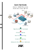
Quick Start Guide CISCO 2610 ROUTER CABLING AND SETUP Windows NT 4.
1 Take Out What You Need This guide explains how to cable and set up your Cisco 2610 router with the following configuration: • 8- or 16-port internal analog modem in the network module slot. • 2 empty WAN interface card slots with a blank panel in each slot. Note: If your router has a different hardware configuration, refer to the Cisco 2600 Series Hardware Installation Guide for information on how to install and set up your router. Begin by taking out the following items from the box.
1 Take Out What You Need (continued) Cables and Power Cord 1 yellow Ethernet 10BaseT cable (to connect to a 10BaseT hub) 1 flat, light-blue console cable with 1 RJ-45 adapter, labeled TERMINAL (RJ-45-to-DB-9 or RJ-45-to-DB-25) 8 or 16 pink modem cables (RJ-11) 3 1 black power cord
2 Connect Cables SERIAL 1 100-240V– 1A 50/60 Hz 47 W SERIAL 1 SERIAL 0 CONN SEE MANUAL BEFORE INSTALLATION WIC CONN 2A/S SERIAL 0 CONN CONN WIC 2T SEE MANUAL BEFORE INSTALLATION MODEMS 16AM IN USE 15 14 13 12 11 10 9 8 5 4 3 2 1 0 IN USE LINK ETHERNET 0 ACT CONSOLE 7 6 Installing a Network Module Use this procedure, if required, to install an 8- or 16-port analog modem network module in a Cisco 2610 router.
2 Connect Cables (continued) MODEMS 16AM 15 14 13 12 11 10 9 8 7 6 5 4 3 2 1 0 IN USE SERIAL 1 100-240V– 1A 50/60 Hz 47 W SERIAL 1 SERIAL 0 IN USE CONN EN WIC CONN 2A/S SERIAL 0 CONN SEE MANUAL BEFORE INSTALLATION CONN WIC 2T SEE MANUAL BEFORE INSTALLATION LINK ETHERNET 0 ACT CONSOLE AUX Ethernet 10BaseT port (RJ-45) 10BaseT cable 5 Ethernet hub (sold separately) Connect the Ethernet Cable Position the router so you can reach the rear panel.
2 Connect Cables (continued) MODEMS 16AM 15 14 13 12 11 10 9 8 IN USE 7 6 5 4 3 2 1 0 EN SERIAL 1 100-240V– 1A 50/60 Hz 47 W SERIAL 1 IN USE CONN SERIAL 0 WIC CONN 2A/S SERIAL 0 CONN SEE MANUAL BEFORE INSTALLATION CONN WIC 2T SEE MANUAL BEFORE INSTALLATION LINK ETHERNET 0 CONSOLE AUX Console port (RJ-45) RJ-45-to-DB-9 or RJ-45-to-DB-25 adapter 6 Connect the Console Cable 1 Connect the light-blue console cable to the light-blue port labeled CONSOLE on the rear panel o
2 Connect Cables (continued) MODEMS 16AM 15 14 13 12 11 10 9 8 IN USE 7 6 5 4 3 2 1 0 EN SERIAL 1 100-240V– 1A 50/60 Hz 47 W SERIAL 1 IN USE SERIAL 0 CONN WIC CONN 2A/S SEE MANUAL BEFORE INSTALLATION SERIAL 0 CONN CONN WIC 2T SEE MANUAL BEFORE INSTALLATION LINK ETHERNET 0 CONSOLE AUX Analog modem port (RJ-11) RJ-11 modem cable RJ-11 jack Connect the Modem Cables The Cisco 2610 router comes with an 8- or 16-port internal analog modem module.
2 Connect Cables (continued) MODEMS 16AM 15 14 13 12 11 10 9 8 IN USE 7 6 5 4 3 2 1 0 EN SERIAL 1 100-240V– 1A 50/60 Hz 47 W SERIAL 1 IN USE CONN SERIAL 0 SEE MANUAL BEFORE INSTALLATION WIC CONN 2A/S SERIAL 0 CONN CONN WIC 2T SEE MANUAL BEFORE INSTALLATION LINK ETHERNET 0 ACT CONSOLE AUX Power switch Power outlet Connect Power and Turn On the Router 8 1 Connect one end of the black power cord to the power connector on the router’s rear panel.
3 Run Cisco Fast Step 12 9 3 6 Timesaver Cisco Fast Step software prompts you for network information according to the routing protocols you select. Before you run the software, make sure you have this information available or know where to get it (usually from the network administrator). Once installed, the Cisco Fast Step Setup program starts automatically. Follow the onscreen instructions to guide you through configuring and testing the router.
4 Finish the Cabling This section applies only if your are connecting more than one modem. If you connected one modem in the procedure on page 7, you are now ready to cable the rest of your modems. How you do this depends on the way you organize your workspace and your own personal preferences. The following suggested procedure helps you simplify the job by keeping the connections neat and orderly and by providing a reliable process. 1 Make sure you can reach the router’s rear panel.
5 Network Information - Optional This appendix is provided to help you gather and organize the information you need to run the Cisco Fast Step software on page 9. Login/Security Information Router name: Router password (for read-only access): Super secret password (for read/write access): IP Routing IP address list: LAN-Side IP Address IP address: 11 Subnet mask: Dial-In-Side IP Address Specify the starting range (up to 16 in range) or IP address list.
5 Network Information - Optional (continued) IPX Routing IPX network number of LAN side of router: IPX Frame type (802.3, 802.
Corporate Headquarters Cisco Systems, Inc. 170 West Tasman Drive San Jose, CA 95134-1706 USA http://www.cisco.com Tel: 408 526-4000 800 553-NETS (6387) Fax: 408 526-4100 European Headquarters Cisco Systems Europe s.a.r.l. Parc Evolic, Batiment L1/L2 16 Avenue du Quebec Villebon, BP 706 91961 Courtaboeuf Cedex France http://www-europe.cisco.com Tel: 33 1 6918 61 00 Fax: 33 1 6928 83 26 Americas Headquarters Cisco Systems, Inc. 170 West Tasman Drive San Jose, CA 95134-1706 USA http://www.cisco.