
User guide


Maintaining the Cisco 2500 Series Access Server B-13
Closing the Chassis
Replacing the Cover
After you perform the maintenance for your system, take the following steps to replace the
cover:
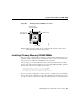
Step 1 Position the two chassis sections as shown in Figure B-7.
Step 2 Referring to Figure B-7, press the two chassis sections together and ensure the
following:
• The top section fits into the rear of the bottom section. (See A in Figure B-7.)
• The bottom section fits into the front of the top section. (See B in Figure B-7.)
• Each side of the top and bottom sections fits together. (See C in Figure B-7.)
Caution To fit the two sections together, it may be necessary to work them together at one
end and then the other, working back and forth; however, use care to prevent bending of the
chassis edges.
Figure B-7 Replacing the Chassis Cover
Step 3
When the two sections fit together snugly, turn the chassis so that the bottom is
facing up, with the front panel toward you.
Step 4 Replace the cover screw. Tighten the screw to no more than 8 or 9 inch/pounds of
torque.
H3560
FrontRear
Left end
toward you
Top section
Bottom section
A
B
C