
User guide


B-12 Cisco 2500 Series Access Server User Guide
Closing the Chassis
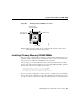
Step 8 Using the system card orientation shown in Figure B-6, position the new SIMM
so that the polarization notch is located at the right end of the SIMM socket. Note
that the orientation of the system card is the opposite of that shown in Figure B-2.
Caution To prevent damage, note that some Flash SIMMs have the components mounted
on the rear side; therefore, when inserting the SIMM, always use the polarization notch as
a reference and not the position of the components on the SIMM.
Step 9 Insert the new SIMM by sliding the end with the metal fingers into the appropriate
SIMM connector socket (CODE 0 or CODE 1 shown in Figure B-2) at
approximately a 45-degree angle to the system card. Gently rock the SIMM back
into place until the latch on either side snaps into place. Do not use excessive force
because the connector could break.
Step 10 Replace the access server cover using the procedure in the following section,
“Closing the Chassis.”
Step 11 Connect the access server to a console terminal.
Step 12 Turn on the power to the chassis.
If error messages relating to memory display, repeat these Steps, taking care to
firmly seat the SIMM in the socket.
Closing the Chassis
This section describes the procedure for closing the chassis.
Tools Required
Following are the tools required for replacing the cover:
• Medium-size flat-blade screwdriver (1/4 inch [0.625 cm])
• Size M 3.5 hex-head nut driver (optional)