
User guide


Maintaining the Cisco 2500 Series Access Server B-3
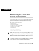
Opening the Chassis
Step 4 Remove the single screw located on the bottom of the chassis (on the chassis side
closest to you). Note that the chassis is comprised of two sections: top and bottom.
Step 5 If required, insert a medium-size flat-blade screwdriver into the slots shown in
Figure B-1, Part A, and gently rotate the blade so that the top and bottom sections
separate slightly.
Step 6 Holding the chassis with both hands, position it as shown in Figure B-1, Part B.
Step 7 Gently pull the top section away from the bottom section. (See Figure B-1, Part
B.) The fit is very snug, so it may be necessary to work the chassis sections apart
at one end and then the other, working back and forth.
Figure B-1 Chassis Cover Removal
Step 8
When the top cover is off, set it aside. Figure B-2 shows the layout of the system
card, which is attached to the bottom section of the chassis.
SERIES
Slot
H3556
Screw Slot
A
Flat-blade screwdriver
H3557
FrontRear
Left end
toward you
B
Top section
Bottom section