
Technical data


Step 7—Testing Async Shell Connections
Dial Solutions Quick Configuration Guide
2-22
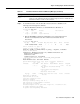
Every Q.931 message indicates whether the message was transmitted by the access server (TX ->)
or received by the access server (RX <-). Table 2-2 shows the most common message types used for
opening and closing connections. Information elements exist within each message type, as described
in Table 2-3.
ISDN setup messages contain different information elements. See Table 2-3.
Table 2-2 Debug Q.931 ISDN Messages
Message Type Description
SETUP
Indicates that a SETUP message has been received to initiate call establishment between
PSTN end devices.
A key element to observe within the call setup message is the bearer capability.
CALL_PROC
Call proceeding. The network attempts to service the call. The switch is attempting to set up
a call through the ISDN network backbone.
CONNECT
The called side transmits “CONNECT” when the connection is made. The side that transmits
“
CONNECT” is usually the side that receives the call, which is the called party.
CONNECT_ACK
Connect acknowledgment. Transmitted by the calling side to indicate that the “CONNECT”
message was received.
DISCONNECT
Indicates that the transmitting side is ending the call. This messages indicates who dropped
the call.
RELEASE
Indicates that the sending equipment is releasing the call and the associated channel.
RELEASE_COMP
Release complete. Indicates that the ISDN network has received the “RELEASE” message.
Table 2-3 Information Elements within an ISDN Setup Message
Message Description
Bearer Capability
Indicates what kind of service the caller is requesting. For example, a 64K data call is
indicated by the bearer capability of 0x8890. An analog voice call is indicated by the value
0x8090A2.
pd
Indicates the protocol discriminator number, which is 8 for Q.931 messages.
callref
A number used by the access server and the switch to reference the call. Indicates the call
reference number in hexadecimal format. The field value indicates the number of calls made
from the router (outgoing calls) or the network (incoming calls). Note that the originator of
the SETUP message sets the high-order bit of the call reference number to 0.
The destination of the connection sets the high-order bit to 1 in subsequent call control
messages, such as the
CONNECT message. For example, callref = 0x04 in the request
becomes callref = 0x84 in the response.
Cause i
Indicates the Information Element Identifier. The value depends on the field with which it is
associated. Refer to the ITU-T Q.931 specification for details about the possible values
associated with each field for which this identifier is relevant.
Channel ID
Indicates the Channel Identifier. The value 83 indicates any channel, 89 indicates the B1
channel, and 8A indicates the B2 channel. For more information about the Channel
Identifier, refer to ITU-T Recommendation Q.931.
Calling Party
Number
Identifies the phone number of the device that initiated the call.
In this case study,
5551111 is the directory number assigned to the telephone line used by
the test PC.