
Technical data


Dial Case Study Overview 1-7
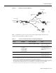
Call Processing Components
Dialer Cloud Subnet
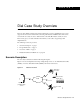
IP subnet 10.1.254.0/24 is assigned to the PSTN/ISDN. The static IP addresses are described in
Table 1-4. See the column “WAN IP Address.” The PSTN/ISDN becomes a “dialer cloud” from the
Cisco IOS perspective. Dialer interfaces are used to connect to this dialer cloud. BRI and PRI
interfaces are also dialer interfaces and use the same dial-on-demand routing (DDR) mechanisms to
open and close circuit-switched connections.
A key design decision in this case study is to number the dialer cloud subnet. (That is, IP
unnumbered is not used on these interfaces.) Numbering the dialer cloud ports to match the remote
LAN supported by the same remote device is part of our design strategy to simplify administration.
For example, remote subnet 10.1.3.0/24 is connected to the same remote site as dialer cloud node
10.1.254.3. IP node 10.1.254.4 supports IP subnet 10.1.4.0/24.
On the Cisco AS5300, all the individual serial channel interfaces are grouped together under one
master dialer interface. As the individual remote sites connect, their configurations must coordinate
with the configuration of the master dialer interface.
Tahoe and Austin LAN Subnets
IP subnet 10.1.3.0/24 is assigned to the Ethernet connected to the Cisco 766 (soho-tahoe). IP subnet
10.1.4.0/24 is assigned to the Cisco 1604 (robo-austin) Ethernet. Each site that supports a distinct IP
subnet must be assigned its own distinct IP subnet address space. Routers with LANs behind them
must have their own distinct IP subnets when not using PAT.
These remote LAN routers point to the central site as the default route. The hq-sanjose NAS is
configured with static routes to the remote IP subnets.
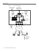
Call Processing Components
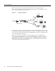
Figure 1-5 illustrates the connectivity path as calls come into the Cisco AS5300. The contents inside
the dotted square box are the internal components of the Cisco AS5300. Both analog modem and
digital calls enter the Cisco AS5300 via the E1/T1 controllers. Incoming modem calls are connected
with the integrated modems and routed to the asynchronous interfaces. Incoming sync PPP calls are
connected to the individual serial channels (for example, S0:1 and S0:2).
As shown in Figure 1-5, one PPP/modem user consumes resources from one channel, one integrated
modem, one line, and one asynchronous interface. An ISDN B-channel user connects directly via a
channel of the T1 and a serial B-channel. The group-async and dialer interfaces are used to control
the interfaces’ behavior and configuration of async and serial channels.