
Technical data


Design Architecture
Dial Solutions Quick Configuration Guide
1-6
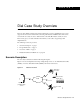
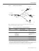
Using the subnetting plan and topologies shown in the previous tables and figures, a router naming
and addressing plan is created in Table 1-4. Notice that the IP addresses are derived directly from the
subnet plan.
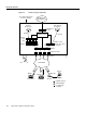
IP Subnet Rationale
This section describes each IP subnet and its design criteria. IP route summarization occurs at the
gateway that connects the NAS to the IP backbone. IP range 10.1.0.0/16 is propagated to the
backbone.
Hq-access Subnet
IP subnet 10.1.1.0/24 is assigned to the Ethernet connected to the Cisco AS5300. If additional access
servers and POP management devices are needed, they are assigned to this IP subnet. Using one
subnet for the entire headquarters dial access POP simplifies network design.
NAS Loopback 0 Subnet
IP subnet 10.1.2.0/24 is assigned to the loopback interface on the Cisco AS5300. This is the subnet
used to host the remote node IP addresses. The access server has an IP pool range of 10.1.2.2 through
10.1.2.97.
Remote nodes dialing in request addresses from the Cisco AS5300’s local IP address pool.
This IP pool behaves like an address server handing out IP addresses to remote nodes during IPCP
negotiation (a component of PPP).
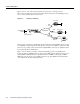
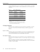
Table 1-4 Router IP Addressing Plan
Router Name
1
1. Using the subnetting plan and topologies shown in the previous tables and
figures, a router naming and addressing plan is created in are now assigned
host names.
WAN
IP Address
Ethernet
IP Address
hq-sanjose 10.1.254.1
255.255.255.0
10.1.1.10
255.255.255.0
soho-tahoe 10.1.254.3
255.255.255.0
10.1.3.1
255.255.255.0
robo-austin 10.1.254.4
255.255.255.0
10.1.4.1
255.255.255.0
...
2
2. These dots mean that you can add additional subnets and remote LANs to
this solution. This case study gives you a basic foundation from which you
can scale to support larger dial implementations.
... ...
... ... ...