
Technical data


Dial Case Study Overview 1-5
Layer 3 IP Design
Layer 3 IP Design
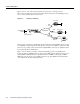
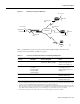
This case study uses PPP to transport IP packets across the PSTN and into the end-user devices
(remote LAN or remote node). IPCP is the specific service enabled over the PPP links. To deliver
this service, the case study uses address space from 10.1.0.0 /16. See the following figures and tables
for the IP subnetting plan.
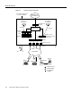
Figure 1-4 IP Subnetting Diagram
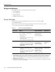
Table 1-3 IP Subnetting Plan
Subnet Name Assigned Subnet Location
Hq-access 10.1.1.0 /24 Hq-access Ethernet
NAS loopback 0
1
1. NAS = network access server. The loopback subnet supports the remote node devices.
10.1.2.0 /24 Loopback interface
inside the Cisco AS5300
Dialer cloud 10.1.254.0 /24 Public switched
telephone network
Tahoe LAN 10.1.3.0 /24 Tahoe Ethernet
Austin LAN 10.1.4.0 /24 Austin Ethernet
...
2
2. Thesedots mean that you can add additional subnets and remote LANs to this solution.
This case study gives you a basic foundation from which you can scale to support
larger dial implementations.
... ...
... ... ...
16023
Dialer cloud
(PSTN/ISDN)
10.1.254.0/24
10.1.3.0/24
Tahoe LAN
10.1.4.0/24
Austin LAN
10.1.1.0/24
Hq-access
10.1.2.0/24
NAS loopback 0