
Technical data


CHAPTER
Routing across Modem Lines 6-1
6
Routing across Modem Lines
Previous chapters in this guide have focused on configuring an access server to allow remote node
computers to dial in to a network. This chapter describes how to configure two access servers so that
one places an outgoing call and a second access server accepts. The access server initiating the call
establishes a dial-on-demand routing (DDR) connection to the answering access server when
packets that are considered “interesting” (IP unicast packets) pass through the interface configured
to initiate a call.
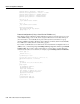
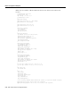
Figure 6-1 shows a simple DDR scenario between two access servers. In this example, an IP host on
network 172.16.20.0 opens a connection session with a host on IP network 172.16.10.0. The two
access servers exchange routing information using the RIP routing protocol (although RIP
broadcasts cannot initiate a call or keep the line active). This figure is referred to throughout this
chapter and the sample configurations are based on this figure.
Figure 6-1 Asynchronous Dial-on-Demand Routing Network Design
In the preceding example, the answering access server is Snoopy on IP network 172.16.10.0, and the
dialing access server is Woodstock on IP network 172.16.20.0. You must configure the answering
access server first, then configure the dialing access server.
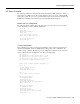
Configuring the Answering Access Server
In this configuration, the answering access server has the name Snoopy. This name is passed by this
access server in a PPP authentication process. Each access server has the name of the other access
server defined in its username database (with the username command). That is, the dialing access
server—Woodstock—must have a username Snoopy defined, and the answering access
server—Snoopy—must have the username Woodstock defined. Refer to the section “Configuring
Security for the Access Server Answering the DDR Call.”
IP network 172.16.10.0 IP network 172.16.20.0
Snoopy Woodstock
Modem Modem
S4903
Answering side Dialing side