About This Guide This chapter discusses the objectives, audience, organization, and conventions of the Dial Solutions Quick Configuration Guide. Cisco documentation and additional literature are available on the Documentation CD-ROM. The CD is updated and shipped monthly so it might be more current than printed documentation. To order the Documentation CD, contact your local sales representative or call Customer Service. The CD is available both as a single CD and as an annual subscription.
Audience Audience This guide is intended primarily for the following audiences: • System administrators who are familiar with the fundamentals of router-based internetworking and who are responsible for installing and configuring internetworking equipment, but who might not be familiar with the specifics of Cisco products or the routing protocols supported by Cisco products. • • Customers who support dial-in users, but who have little experience with router-based networks.
Document Conventions Examples use the following conventions: Convention Description screen Shows an example of information displayed on the screen. boldface screen Shows an example of information that you must enter. < Nonprinting characters, such as passwords, appear in angled brackets. > ! [ Exclamation points at the beginning of a line indicate a comment line. They are also displayed by the Cisco IOS software for certain processes.
Command Syntax Conventions Command Syntax Conventions Command descriptions use the following conventions: Convention Description boldface Indicates commands and keywords that are entered literally as shown. italics Indicates arguments for which you supply values; in contexts that do not allow italics, arguments are enclosed in angle brackets (< >). [x] Keywords or arguments that appear within square brackets are optional.
Where to Go for More Information • Modem: From North America, 408 526-8070; from Europe, 33 1 64 46 40 82. Use the following terminal settings: VT100 emulation; databits: 8; parity: none; stop bits: 1; and connection rates up to 28.8 kbps. For a copy of CCO’s Frequently Asked Questions (FAQ), contact cco-help@cisco.com. For additional information, contact cco-team@cisco.com.
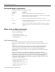
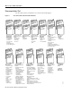
Where to Go for More Information Documentation Set The Cisco IOS software documentation set is shown in the following figure: Cisco IOS Software Documentation Modules Module FC Configuration Guide Module P1C Configuration Guide Module P2C Configuration Guide Module P3C Configuration Guide Module FR Command Reference Module P1R Command Reference Module P2R Command Reference Module P3R Command Reference Module FC/FR: Module P1C/P1R: Configuration Network Protocols, Fundamentals Part 1 • Configuratio
Using Cisco IOS Software This chapter provides helpful tips for understanding and configuring Cisco IOS software using the command-line interface (CLI). • • • • Getting Help Understanding Command Modes Using the No and Default Forms of Commands Saving Configuration Changes For an overview of Cisco IOS software configuration, refer to the Configuration Fundamentals Configuration Guide.
Getting Help Finding Command Options This section provides an example of how to find and display the syntax for a command. The syntax can consist of optional or required keywords. To display keywords for a command, enter a question mark (?) at the configuration prompt, or after entering part of a command followed by a space. The Cisco IOS software displays a list of keywords available along with a brief description of the keywords.
Getting Help Table 1 How to Find Command Options (Continued) Command Comment Router(config-controller)# cas-group ? <0-23> Channel number Router(config-controller)# cas-group Enter the command that you want to configure for the controller. In this example, the cas-group command is used. Enter a ? to display what you must enter next on the command line. In this example, you must enter a channel number from 0 to 23.
Getting Help Table 1 How to Find Command Options (Continued) Command Comment Router(config-controller)# cas-group 1 timeslots 1-24 type e&m-fgb ? dtmf DTMF tone signaling mf MF tone signaling service Specify the type of service Router(config-controller)# cas-group 1 timeslots 1-24 type e&m-fgb In this example, the e&m-fgb keyword is entered. After you enter the e&m-fgb keyword, enter a ? to display what you must enter next on the command line.
Understanding Command Modes Understanding Command Modes The Cisco IOS user interface is divided into many different modes. The commands available to you at any given time depend on which mode you are currently in. Entering a question mark (?) at the system prompt allows you to obtain a list of commands available for each command mode. When you start a session on the router, you begin in user mode, often called EXEC mode. Only a limited subset of the commands are available in EXEC mode.
Using the No and Default Forms of Commands Table 2 Command Mode ROM monitor Summary of Main Command Modes (Continued) Access Method Prompt Exit Method From privileged EXEC mode, use the reload EXEC command. Press the Break key during the first 60 seconds while the system is booting. > To exit to user EXEC mode, type continue. For more information regarding command modes, refer to the “Using the Command Line Interface” chapter of the Configuration Fundamentals Configuration Guide.
C H A P TER 1 Dial Case Study Overview This case study builds a dial-up network environment using one Cisco AS5300. The access server supports remote users and remote LANs connecting with modems and ISDN routers. The remote routers in this case study are a Cisco 1604 and Cisco 766. Only IP and basic security are used. This exercise gives you a basic foundation from which you can scale to support larger dial implementations.
Scenario Description Figure 1-2 shows some of the physical elements present at layer 1 of the Open System Interconnection (OSI) reference model. The public switched telephone network (PSTN) provides the core interconnecting fabric between devices.
Scenario Description Figure 1-3 OSI Layer 2 and Layer 3 Elements 10.1.3.1/24 Ethernet 10.1.254.3/24 PPP 10.1.254.4/24 PPP 10.1.1.10/24 PSTN/ISDN Ethernet 10.1.254.1/24 PPP 10.1.4.1/24 Remote PC PPP 15582 Headquarters IP network Table 1-1 summarizes the types of services provided by the headquarters POP to the remote nodes and sites. For more information, see Table 1-2 on page 4.
Design Architecture Design Architecture The following sections provide the framework for this case study: • • • • Service Definitions Layer 3 IP Design IP Subnet Rationale Call Processing Components Service Definitions In this case study, the Cisco AS5300 offers three basic services: async shell, async PPP, and sync PPP. See Table 1-2. These services are based on real needs as requested by the remote sites. To access these services, remote devices connect to the Cisco AS5300 via the PSTN.
Layer 3 IP Design Layer 3 IP Design This case study uses PPP to transport IP packets across the PSTN and into the end-user devices (remote LAN or remote node). IPCP is the specific service enabled over the PPP links. To deliver this service, the case study uses address space from 10.1.0.0 /16. See the following figures and tables for the IP subnetting plan. Figure 1-4 IP Subnetting Diagram 10.1.1.0/24 Hq-access 10.1.3.0/24 Tahoe LAN Dialer cloud (PSTN/ISDN) 10.1.254.0/24 10.1.4.
Design Architecture Using the subnetting plan and topologies shown in the previous tables and figures, a router naming and addressing plan is created in Table 1-4. Notice that the IP addresses are derived directly from the subnet plan. Table 1-4 Router IP Addressing Plan WAN IP Address Ethernet IP Address hq-sanjose 10.1.254.1 255.255.255.0 10.1.1.10 255.255.255.0 soho-tahoe 10.1.254.3 255.255.255.0 10.1.3.1 255.255.255.0 robo-austin 10.1.254.4 255.255.255.0 10.1.4.1 255.255.255.0 ...2 ... ..
Call Processing Components Dialer Cloud Subnet IP subnet 10.1.254.0/24 is assigned to the PSTN/ISDN. The static IP addresses are described in Table 1-4. See the column “WAN IP Address.” The PSTN/ISDN becomes a “dialer cloud” from the Cisco IOS perspective. Dialer interfaces are used to connect to this dialer cloud. BRI and PRI interfaces are also dialer interfaces and use the same dial-on-demand routing (DDR) mechanisms to open and close circuit-switched connections.
Design Architecture Figure 1-5 Call Processing Components Cisco IOS terrain inside the Cisco AS5300 Headquarters intranet/internet Interface dialer controlling the D channels Interface group-async Fast Ethernet interface Routing and switching engine Cloning Cloning Interface async Lines Interface serial channels S0:1, S0:2… (B channels) Modems TDM bus Controllers T1/E1 Cisco AS5300 BRI line Cisco 1604 15042 PRI lines PSTN/ISDN Remote PC BRI line Cisco 766 POTS line Modem = ISDN B chan
Overview of Tasks Overview of Tasks The network devices in this case study are manually configured using Cisco IOS software. The automatic Cisco IOS setup script is not used. This setup script usually runs when no startup configuration is found in NVRAM (for example, when powering up a new router). Here is the action plan to build the network. For step-by-step configuration tasks, refer to the device-specific configuration chapters that follow. Step 1 Set up async shell services on the Cisco AS5300.
Related Documents and Web Tools — Confirming the Final Running Configuration — Saving the Configuration Step 5 Configure the Cisco 766 to dial into the Cisco AS5300. See chapter 4 “Cisco 766 Configuration.
Related Documents and Web Tools • Troubleshooting Engine—Helps you solve common problems involving hardware, configuration, and performance. http://te.cisco.com/cgi-bin/webcgi.exe?New,KB=TE • Cisco AS5x00 Access Server Documentation—Includes software and hardware configuration guides for Cisco’s access server product line. http://www.cisco.com/univercd/cc/td/doc/product/access/acs_serv/index.htm Note These URLs can change without notice.
Related Documents and Web Tools 1-12 Dial Solutions Quick Configuration Guide
C H A P TER 2 Cisco AS5300 Configuration This chapter describes how to configure the Cisco AS5300 to receive calls from the Cisco 1604, Cisco 766, and remote modem users. Site Profile Characteristics Figure 2-1 shows the network topology from the Cisco AS5300’s perspective. Figure 2-1 Network Topology Cisco 766 remote LAN DNS server 10.2.2.3 10.1.1.10 255.255.255.0 Cisco 1604 remoteLAN Four T1 PRI lines PSTN/ISDN Interface dialer 10.1.254.1 255.255.255.
Site Profile Characteristics Table 2-1 provides detailed information about each end of the connection. This is the network administrator’s top-level design table. Table 2-1 Site Characteristics Site Hardware WAN IP Address Ethernet IP Address Assigned Phone Number Host Name/ Username1 Username Password1 Cisco AS53002 10.1.254.1 255.255.255.03 10.1.1.10 255.255.255.0 40855512344 hq-sanjose hq-sanjose-pw Cisco 766 10.1.254.3 255.255.255.0 10.1.3.1 255.255.255.
Site Profile Characteristics Cisco Internetwork Operating System Software IOS (tm) 5300 Software (C5300-JS-M), Version 12.0(x) Copyright (c) 1986-1998 by cisco Systems, Inc. Compiled Tue 07-Jul-98 15:26 by xxxx Image text-base: 0x600088E8, data-base: 0x608F4000 cisco AS5300 (R4K) processor (revision A.04) with 32768K/8192K bytes of memory. Processor board ID 04614948 R4700 processor, Implementation 33, Revision 1.0 (512KB Level 2 Cache) Bridging software. X.25 software, Version 3.0.0.
Overview of Tasks Overview of Tasks Perform the following steps to configure the access server: • Set up asynchronous shell services: — “Step 1—Configuring the Host Name, Password, and Time Stamps” on page 5 — “Step 2—Configuring Local AAA Security” on page 6 — “Step 3—Configuring the Fast Ethernet 100BaseT Interface” on page 8 — “Step 4—Commissioning the T1 Controllers” on page 10 — “Step 5—Configuring the Serial Channels to Let Modem Calls Come in” on page 14 — “Step 6—Configuring the Modems and Lines”
Step 1—Configuring the Host Name, Password, and Time Stamps Step 1—Configuring the Host Name, Password, and Time Stamps Assign a host name to the Cisco AS5300, enable basic security, and turn on time stamping. Configuring a host name allows you to distinguish between different network devices. Enable passwords allow you to prevent unauthorized configuration changes. Time stamps help you trace debug output for testing connections.
Step 2—Configuring Local AAA Security • Enter the show running command: hq-sanjose# show running Building configuration... Current configuration: ! version 12.0 service timestamps debug datetime msec service timestamps log datetime msec service password-encryption ! hostname hq-sanjose ! enable secret 5 $1$.voA$9/8.Zoil3jeWJMP6hEE6U0 ! ----- snip ---- Tips If you have trouble: • • • Make sure Caps Lock is off. Make sure you entered the correct passwords. Passwords are case sensitive.
Configure Configure To configure local AAA security, use the following commands beginning in global configuration mode: Step Command Purpose 1 hq-sanjose(config)# username joe-admin password joe-password Create a local login database and username for yourself1. This step also prevents you from getting locked out of the access server. 2 hq-sanjose(config)# aaa new-model Initiate the AAA access control system. This step immediately locks down login and PPP authentication.
Step 3—Configuring the Fast Ethernet 100BaseT Interface ! aaa new-model aaa authentication login default local aaa authentication ppp default if-needed local enable secret 5 $1$.voA$9/8.Zoil3jeWJMP6hEE6U0 ! username joe-admin password 7 ! ----- snip ---- Step 3—Configuring the Fast Ethernet 100BaseT Interface Assign an IP address, line speed, and duplex mode to the Fast Ethernet interface. The Fast Ethernet interface supports 10- and 100-Mbps speeds.
Verify • Try pinging a device in your network, such as a backhaul router or the backbone gateway: hq-sanjose# ping 10.1.1.1 Type escape sequence to abort. Sending 5, 100-byte ICMP Echos to 10.1.1.1, timeout is 2 seconds: !!!!! Success rate is 100 percent (5/5), round-trip min/avg/max = 4/5/8 ms • Enter the show interface fastethernet 0 command to see detailed interface information. Look for the display field “FastEthernet 0 is up, line protocol is up.
Step 4—Commissioning the T1 Controllers Step 4—Commissioning the T1 Controllers Configure the T1 controllers to allow calls to come into the access server. You must specify the following information for each controller: framing type, line code type, clock source, and timeslot assignments. Configure To configure the controllers, use the following commands beginning in global configuration mode: Step Command Purpose 1 hq-sanjose(config)# isdn switch-type primary-ni Enter your telco’s switch type.
Verify Verify To verify the configuration: • Use the show controller t1 command. The output from this command enables you to determine when and where errors occur. See the display field “Data in current interval.” hq-sanjose# show controller t1 T1 0 is up. No alarms detected. Version info of slot 0: HW: 2, Firmware: 16, PLD Rev: 0 Manufacture Cookie Info: EEPROM Type 0x0001, EEPROM Version 0x01, Board ID 0x42, Board Hardware Version 1.
Step 4—Commissioning the T1 Controllers EEPROM Type 0x0001, EEPROM Version 0x01, Board ID 0x42, Board Hardware Version 1.0, Item Number 73-2217-4, Board Revision A0, Serial Number 07557185, PLD/ISP Version 0.0, Manufacture Date 17-Dec-1997. Framing is ESF, Line Code is B8ZS, Clock Source is Internal.
Verify • Enter the show running command: hq-sanjose# show running Building configuration...
Step 5—Configuring the Serial Channels to Let Modem Calls Come in Step 5—Configuring the Serial Channels to Let Modem Calls Come in The async shell service is the first service to enable. Configure the D channels to allow incoming voice calls to be routed to the integrated modems. In the section “Configuration DDR,” the D channel configuration is expanded to also accept ISDN synchronous PPP calls from the remote offices. Cisco recommends getting modem users up first.
Verify Verify To verify the configuration: • Launch a voice call into the access server using a standard POTS telephone. If you hear modem squelch (tone) from the access server’s internal modem, the configuration works. See Figure 2-2. Figure 2-2 PSTN/ISDN Voice Test Call POTS Cisco AS5300 receiving analog telephone call • Standard POTS telephone dialing 555-1234 15987 PRI 555-1234 Enter the show interface serial 0:23 command.
Step 5—Configuring the Serial Channels to Let Modem Calls Come in • Enter the show isdn status command to view the ISDN layer information. This output shows that layer 1 and layer 2 are enabled and active. Layer 3 shows the number of active ISDN calls, which there are none currently.
Verify Activated dsl 0 State (0=Idle 1=Propose 2=Busy 3=Reserved 4=Restart 5=Maint) 0 0 0 0 0 0 0 0 0 0 0 0 0 0 0 0 0 0 0 0 0 0 0 3 3 3 3 3 3 3 3 Channel (1-31) Service (0=Inservice 1=Maint 2=Outofservice) 0 0 0 0 0 0 0 0 0 0 0 0 0 0 0 0 0 0 0 0 0 0 0 2 2 2 2 2 2 2 2 ISDN Se2:23, Channel (1-31) Activated dsl 0 State (0=Idle 1=Propose 2=Busy 3=Reserved 4=Restart 5=Maint) 0 0 0 0 0 0 0 0 0 0 0 0 0 0 0 0 0 0 0 0 0 0 0 3 3 3 3 3 3 3 3 Channel (1-31) Service (0=Inservice 1=Maint 2=Outofservice) 0 0 0 0 0 0 0 0
Step 6—Configuring the Modems and Lines ! interface Serial1:23 no ip address no ip directed-broadcast isdn incoming-voice modem ! interface Serial2:23 no ip address no ip directed-broadcast isdn incoming-voice modem ! interface Serial3:23 no ip address no ip directed-broadcast isdn incoming-voice modem ! ---- snip ---- Tips If you have trouble: • • • Be sure you have the correct ISDN switch type configured. • Make sure the show controller t1 command’s current output shows no errors occurring.
Verify Verify Enter the show running command to verify the configuration: hq-sanjose# show running Building configuration... Current configuration: ---- snip ---! line 1 96 autoselect during-login autoselect ppp modem InOut ---- snip ---- Step 7—Testing Async Shell Connections Now you are ready to send the first modem call into the Cisco AS5300. This step shows you how to perform the test and track the async data path taken by a single modem call.
Step 7—Testing Async Shell Connections Figure 2-3 Test Lab Environment POTS PSTN/ISDN Step 2 Call atdt5551234 using the terminal emultion program PRI 555-1234 RS-232 Step 3 Interpret debug messages Step 1 Modem Cisco AS5300 receiving call from test PC RS-232 console Test PC 15990 Step 1 Enter debug Administrator's PC commands (configuration and logging) Enter the following debug commands on the Cisco AS5300 to debug calls landing on the integrated modems.
Step 7—Testing Async Shell Connections Note The modem attached to the test PC sends out “CONNECT 24000/REL - MNP” The Cisco AS5300 sends out “User Access Verification,” “Username:,” and “Password:.” These messages are confirmation that you have end-to-end async shell connectivity. Step 3 For educational purposes, look at and interpret the debug messages that appear on the administrator’s terminal screen as a result of Step 2. As the modem call came into the access server, this debug output was created.
Step 7—Testing Async Shell Connections Every Q.931 message indicates whether the message was transmitted by the access server (TX ->) or received by the access server (RX <-). Table 2-2 shows the most common message types used for opening and closing connections. Information elements exist within each message type, as described in Table 2-3. Table 2-2 Debug Q.
Step 7—Testing Async Shell Connections Table 2-3 Information Elements within an ISDN Setup Message (Continued) Message Description Called Party Number Identifies the called phone number that is used to reach another device. Step 4 In this case study, 5551234 is the directory number assigned to the Cisco AS5300. The test PC dialed this number to make a modem connection. To determine the status of the modem call connected to the Cisco AS5300, use the following modem management commands.
Step 7—Testing Async Shell Connections • Enter the show modem log 1/1 command to view the information logged for modem 1/1. The time stamps show when the event occurred. The most current events begin at the bottom of the output. hq-sanjose# show modem log 1/1 Modem 1/1 Events Log: 20:40:45: Startup Response: Microcom (Managed) Modem (boot) firmware = 2.2(8) (1.
Step 7—Testing Async Shell Connections • Enter the show controller t1 0 call-counters command, which shows you the DS0 timeslot used to carry the modem call. This example shows that timeslot 1 has accepted one call for a total duration of 1 minute 30 seconds.
Step 7—Testing Async Shell Connections • To further troubleshoot modem problems, connect to a modem’s out-of-band management port. For Microcom modems, use the modem at-mode slot/port command. For MICA modems, use the show modem operational-status slot/port command and the show modem configuration slot/port command. hq-sanjose# modem at-mode 2/15 You are now entering AT command mode on modem (slot 2 / port 15). Please type CTRL-C to exit AT command mode.
Step 8—Setting Up IP Address Pools Step 8—Setting Up IP Address Pools Create a pool of IP address to support remote nodes dialing in. As remote node devices connect, they request an IP address from the central site. It is important to determine how your intranet/Internet backbone will route packets to the addresses in this pool. There are several ways to do this, such as using addresses off a subnet defined on the access server (for example, on the loopback or Ethernet interface).
Step 9—Configuring the Group-Async Interface Step 9—Configuring the Group-Async Interface The group-async interface is a template, which is used to control the configuration of all the async interfaces on the access server. Async interfaces are lines that are running in PPP mode. An async interface uses the same number as its corresponding line. Configuring the asynchronous interfaces as a group-async saves you time and configuration file size.
Verify aaa authentication ppp default if-needed local enable secret 5 $1$.voA$9/8.Zoil3jeWJMP6hEE6U0 ! username joe-admin password 7 ! async-bootp dns-server 10.2.2.3 10.2.3.
Step 9—Configuring the Group-Async Interface ! interface Serial3:23 no ip address no ip directed-broadcast isdn incoming-voice modem no fair-queue no cdp enable ! interface FastEthernet0 ip address 10.1.1.10 255.255.255.
Step 10—Testing Async PPP Connections Step 10—Testing Async PPP Connections Now you are ready to send the first async PPP modem call into the Cisco AS5300. This step provides you with a picture of the test lab followed by debug output for a successful connection. Figure 2-3 shows the test lab environment used for this test. A test PC makes a PPP modem-to-modem connection with the Cisco AS5300 via the PSTN/ISDN network.
Step 10—Testing Async PPP Connections Step 2 From a terminal emulation program running on the test PC, enter atdt followed by the telephone number assigned to the Cisco AS5300. In this case test, 5551234 is used. atdt5551234 CONNECT 24000/REL - MNP User Access Verification Username: joe-admin Password: joe-password hq-sanjose> Step 3 Interpret the debug messages that appear on the administrator’s terminal screen as a result of Step 2.
Step 10—Testing Async PPP Connections (j) See 21:35:03.978. After LCP negotiates, authentication starts. Authentication must happen before any network protocols, such as IP, are delivered. Both sides authenticate with the method negotiated during LCP. The Cisco AS5300 is authenticating the test PC using CHAP. The test PC is not authenticating the access server in this test case. (k) See 21:35:03.982. Outgoing challenge from hq-sanjose. (l) See 21:35:04.162.
Step 10—Testing Async PPP Connections Note To enhance readability of debug output messages, significant display output fields are highlighted with bold font. hq-sanjose# *Mar 1 21:34:56.958: *Mar 1 21:34:56.962: *Mar 1 21:34:56.970: *Mar 1 21:34:56.978: *Mar 1 21:34:59.722: *Mar 1 21:34:59.726: *Mar 1 21:34:59.730: *Mar 1 21:34:59.730: *Mar 1 21:34:59.734: *Mar 1 21:34:59.746: *Mar 1 21:34:59.746: *Mar 1 21:34:59.786: *Mar 1 21:34:59.790: *Mar 1 21:34:59.794: *Mar 1 21:34:59.794: *Mar 1 21:35:01.
Step 10—Testing Async PPP Connections *Mar 1 21:35:04.162: *Mar 1 21:35:04.170: *Mar 1 21:35:04.182: *Mar 1 21:35:04.186: *Mar 1 21:35:04.190: *Mar 1 21:35:04.194: *Mar 1 21:35:04.282: *Mar 1 21:35:04.282: 06002D0F01) *Mar 1 21:35:04.286: *Mar 1 21:35:04.290: *Mar 1 21:35:04.298: *Mar 1 21:35:04.306: *Mar 1 21:35:04.310: 06002D0F01) *Mar 1 21:35:04.314: *Mar 1 21:35:04.318: 01) *Mar 1 21:35:04.318: 00104) *Mar 1 21:35:04.322: *Mar 1 21:35:04.326: *Mar 1 21:35:04.330: *Mar 1 21:35:04.334: *Mar 1 21:35:04.
Step 11—Configuring DDR Step 11—Configuring DDR Dial-on-demand routing (DDR) provides a mechanism to establish and maintain connectivity over a circuit switched network, such as the PSTN. DDR also supports remote LANs by maintaining IP routes to the remote sites when they are not connected. Configure To configure the dialer interfaces, use the following commands beginning in global configuration mode: Step Command Purpose 1 hq-sanjose(config)# interface dialer 1 hq-sanjose(config-if)# ip address 10.1.
Verify Step Command Purpose 16 hq-sanjose(config-if)# exit Return to global configuration mode. 17 hq-sanjose(config)# dialer-list 2 protocol ip permit Define a DDR dialer-list to allow any IP traffic to maintain the connection. Any IP packet will maintain the DDR session. Minor or extensive tuning of your dialer list might be required to control costs in your environment.3 1. These users will also need a username and password. 2. Other environments might require shorter timeouts.
Step 11—Configuring DDR no ip address no ip directed-broadcast dialer rotary-group 1 isdn incoming-voice modem ! interface Serial2:23 no ip address no ip directed-broadcast dialer rotary-group 1 isdn incoming-voice modem ! interface Serial3:23 no ip address no ip directed-broadcast dialer rotary-group 1 isdn incoming-voice modem ! ---- snip ---! interface Dialer1 ip address 10.1.254.1 255.255.255.
Step 12—Configuring Definitions for Remote LAN Sites Step 12—Configuring Definitions for Remote LAN Sites You must configure additional parameters to enable synchronous PPP services for the remote sites. Each remote site must have the following three entries configured on the Cisco AS5300: • • • Username and password Static route Dialer map to support IP connectivity with the remote peer Table 2-4 summarizes the critical parameters used by DDR, which works primarily at the addressing layer.
Step 12—Configuring Definitions for Remote LAN Sites Verify Enter the show running command: hq-sanjose# show running Building configuration... Current configuration: ! ---- snip ---! username joe-admin password 7 username robo-austin password 7 username soho-tahoe password 7 ! ---- snip ---! interface Dialer1 ip address 10.1.254.1 255.255.255.0 no ip directed-broadcast encapsulation ppp no ip mroute-cache dialer in-band dialer idle-timeout 1800 dialer map ip 10.1.254.
Step 13—Configuring a Backhaul Routing Protocol Step 13—Configuring a Backhaul Routing Protocol Assign a routing protocol and configure its related configuration parameters to integrate with the IP backbone. The dialer network uses static routing.
Step 14—Confirming the Final Running Configuration Step 14—Confirming the Final Running Configuration Here is the final running configuration: hq-sanjose# show running Building configuration... Current configuration: ! version 12.0 service timestamps debug datetime msec service timestamps log datetime msec service password-encryption ! hostname hq-sanjose ! aaa new-model aaa authentication login default local aaa authentication ppp default if-needed local enable secret 5 $1$.voA$9/8.
Step 14—Confirming the Final Running Configuration ! interface Serial0:23 no ip address no ip directed-broadcast dialer rotary-group 1 isdn incoming-voice modem ! interface Serial1:23 no ip address no ip directed-broadcast dialer rotary-group 1 isdn incoming-voice modem ! interface Serial2:23 no ip address no ip directed-broadcast dialer rotary-group 1 isdn incoming-voice modem ! interface Serial3:23 no ip address no ip directed-broadcast dialer rotary-group 1 isdn incoming-voice modem ! interface FastEthe
Step 15—Saving the Configuration ! ip local pool dialin_pool 10.1.2.2 10.1.2.97 ip route 10.1.3.0 255.255.255.0 10.1.254.3 permanent ip route 10.1.4.0 255.255.255.0 10.1.254.4 permanent ! dialer-list 2 protocol ip permit ! ! line con 0 line 1 96 autoselect during-login autoselect ppp modem InOut line aux 0 line vty 0 4 ! end Do not expect your final configuration to look exactly like this one. You must localize for your own network environment.
Step 17—Adding More Remote LAN Sites as Needed Table 2-5 Required Commands for Each Additional Site Command Purpose dialer map ip peer-wan-addr name hostname # A dialer map. Create a user entity in the security database for the remote site, which is appended to a dialer map1. ip route subnet mask wan-addr A static route that points to the dialer map IP address. username hostname password password A username and password that matches the name on the dialer map. 1.
Step 17—Adding More Remote LAN Sites as Needed 2-46 Dial Solutions Quick Configuration Guide
C H A P TER 3 Cisco 1604 Configuration This chapter describes how to configure the Cisco 1604 to dial out to the Cisco AS5300. Site Profile Characteristics Figure 3-1 shows the network topology from the Cisco 1604’s perspective. Figure 3-1 Network Topology Branch office server Headquarters 10.1.254.1 255.255.255.0 10.1.4.1 255.255.255.0 BRI line PC E0 PSTN/ISDN Cisco AS5300 Cisco 1604 Hub 10.1.254.4 255.255.255.0 15579 PC Table 3-1 provides detailed information about the end-to-end connection.
Site Profile Characteristics Cisco IOS Release 12.0 is running inside the router. If the startup configuration is blank, the following screen is displayed at bootup. The automatic setup script is engaged. Enter no when you are asked the question, “Would you like to enter the initial configuration dialog? [yes]: no.” In this case study, the Cisco 1604 is manually configured. The automatic setup script is not used.
Overview of Tasks --- System Configuration Dialog --Would you like to enter the initial configuration dialog? [yes/no]: no Would you like to terminate autoinstall? [yes]: yes Press RETURN to get started! 00:00:17: 00:00:17: 00:00:17: 00:00:17: 00:00:17: 00:00:17: 00:00:17: down 00:00:17: 00:00:44: 00:00:46: 00:00:46: 00:00:47: %QUICC_ETHER-1-LOSTCARR: Unit 0, lost carrier.
Step 1—Configuring the Host Name, Password, and Time Stamps Step 1—Configuring the Host Name, Password, and Time Stamps Assign a host name to the Cisco 1604, enable basic security, and turn on time stamping. Configuring a host name allows you to distinguish between different network devices. Enable passwords allow you to prevent unauthorized configuration changes. Time stamps help you trace debug output for testing connections.
Step 2—Configuring Local AAA Security shutdown ! interface Serial0 no ip address shutdown ! interface BRI0 no ip address shutdown ! ip classless ! ! line con 0 line vty 0 4 login ! • Try logging in with your new enable password. Exit out of enable mode using the disable command. The prompt changes from robo-austin# to robo-austin>. Enter the enable command followed by your password. The show privilege command shows the current security privilege level, which is level 15.
Step 2—Configuring Local AAA Security Configure To configure local AAA security, use the following commands beginning in global configuration mode: Step Command Purpose 1 robo-austin(config)# username joe-admin password joe-password Create a local username for yourself1. This step prevents you from getting locked out of the router when you enable AAA. 2 robo-austin(config)# aaa new-model Enable AAA access control. This step immediately enables login and PPP authentication.
Step 3—Configuring the Ethernet Interface ! username joe-admin password 7 ! interface Ethernet0 no ip address shutdown ! interface Serial0 no ip address shutdown ! interface BRI0 no ip address shutdown ! ip classless ! ! line con 0 line vty 0 4 ! Step 3—Configuring the Ethernet Interface Assign an IP address to the Ethernet interface. Test the interface by pinging it from a PC on the LAN.
Step 3—Configuring the Ethernet Interface Ethernet0 Serial0 10.1.4.1 unassigned YES manual up up YES unset administratively down down In the next example, notice that the status is up but the protocol is down. The following logging message appears at 00:40:20: “Unit 0, lost carrier. Transceiver problem?.”After the administrator plugs the Ethernet cable into the Ethernet port, the interface comes up. See 00:40:25.
Step 4—Configuring BRI Received 2 broadcasts, 0 runts, 0 giants, 0 throttles 0 input errors, 0 CRC, 0 frame, 0 overrun, 0 ignored, 0 abort 0 input packets with dribble condition detected 28 packets output, 2905 bytes, 0 underruns 25 output errors, 0 collisions, 2 interface resets 0 babbles, 0 late collision, 0 deferred 3 lost carrier, 0 no carrier 0 output buffer failures, 0 output buffers swapped out Step 4—Configuring BRI Enable BRI connectivity with the central office switch.
Step 4—Configuring BRI Verify • You should see the following output messages after you enter the no shutdown command. This example shows the BRI0:1 and BRI0:2 states change to “down,” because the previous state was “administratively down.” The BRI0 D channel changes to “up” as it spoofs for the two B channels. After the D channel finds the B channels, the B channels change state to “up.” The Cisco 1604 communicates with the telephone switch and receives its TEI numbers for its two B channels.
Step 5—Configuring DDR Note Notice that the status and protocol for BRI 0 and Ethernet 0 are both up/up, which is what we expect to see. The term manual means that you manually configured the interface since the last reboot. The two B channels (BRI0:1 and BRI0:2) are down because there are no active calls on the BRI interface at this time. Tips If you have trouble: • • Make sure the correct ISDN switch type and SPIDs are configured. Make sure your BRI line is connected to the correct port.
Step 5—Configuring DDR Step Command Purpose 8 robo-austin(config) ip route 0.0.0.0 0.0.0.0 10.1.254.1 permanent Create a static route for the next hop, which is the Cisco AS5300’s WAN port. IP address 10.1.254.1 is used on the Cisco AS5300’s dialer interface. This static route points at the dialer map on the access server’s dialer interface.
Verify 0 incoming call(s) rejected for callback. BRI0:1 - dialer type = ISDN Idle timer (120 secs), Fast idle timer (20 secs) Wait for carrier (30 secs), Re-enable (15 secs) Dialer state is idle BRI0:2 - dialer type = ISDN Idle timer (120 secs), Fast idle timer (20 secs) Wait for carrier (30 secs), Re-enable (15 secs) Dialer state is idle • Enter the show dialer map command to view the static dialer map that was built to the Cisco AS5300.
Step 6—Testing Connections to the Cisco AS5300 ! dialer-list 2 protocol ip permit ! line con 0 line vty 0 4 ! end Tips • To display the actual load currently assigned to the interface, enter the show interface bri 0:1 command. Search for the output field “load x/255.” SNMP can be used to monitor the load on an interface. How you set the threshold depends on each site’s characteristics, such as traffic patterns and WAN costs.
Step 6—Testing Connections to the Cisco AS5300 Figure 3-2 shows the actual test lab environment used in this test case. Figure 3-2 Test Lab Environment 10.1.254.1 PSTN/ISDN BRI Cisco AS5300 (hq-sanjose) Test PC 10.1.4.2 DNS server 10.2.2.3 BRI 10.1.254.4 Ethernet Cisco 1604 (robo-austin) Administrator's PC (configuration and logging) Step 1 15988 RS-232 console Turn on the appropriate debugging. Examining the background processes is essential for effective troubleshooting.
Step 6—Testing Connections to the Cisco AS5300 Step 3 Verify that the correct dialer map exists: robo-austin# show dialer map Static dialer map ip 10.1.254.1 name hq-sanjose Step 4 (14085551234) on BRI0 Ping the IP address assigned to the Cisco AS5300’s dialer interface. Notice that the Cisco 1604 (robo-austin) quickly gets 4 of 5 pings back from the Cisco AS5300 (hq-sanjose). After the ping is sent, examine the background processes as displayed by the debug output. robo-austin# ping 10.1.254.
Step 6—Testing Connections to the Cisco AS5300 scenario. (BR0:1 CHAP: (BR0:1 CHAP: I CHALLENGE id 5 len 31 from "hq-sanjose") O RESPONSE id 5 len 32 from "robo-austin") (k) See 08:03:55. The robo-austin PPP peer is successfully authenticated by the hq-sanjose peer. (BR0:1 CHAP: I SUCCESS id 5 len 4) (l) See 08:03:55. MultiLink PPP uses a virtual-access interface to host the bundle. (BR0:1 PPP: Phase is VIRTUALIZED) (m) See 08:03:56.
Step 6—Testing Connections to the Cisco AS5300 08:03:55: BR0:1 LCP: EndpointDisc 1 Local (0x130E01726F626F2D61757374696E) 08:03:55: BR0:1 LCP: I CONFREQ [REQsent] id 7 len 32 08:03:55: BR0:1 LCP: AuthProto CHAP (0x0305C22305) 08:03:55: BR0:1 LCP: MagicNumber 0xE16A73E6 (0x0506E16A73E6) 08:03:55: BR0:1 LCP: MRRU 1524 (0x110405F4) 08:03:55: BR0:1 LCP: EndpointDisc 1 Local (0x130D0168712D73616E6A6F7365) 08:03:55: BR0:1 LCP: O CONFACK [REQsent] id 7 len 32 08:03:55: BR0:1 LCP: AuthProto CHAP (0x0305C22305) 08:
Step 6—Testing Connections to the Cisco AS5300 Sending 5, 100-byte ICMP Echos to 10.2.2.3, timeout is 2 seconds: !!!!! Success rate is 100 percent (5/5), round-trip min/avg/max = 4/7/12 ms Step 7 Use additional commands to verify robo-austin’s connection with hq-sanjose: robo-austin# show dialer map Static dialer map ip 10.1.254.
Step 6—Testing Connections to the Cisco AS5300 0 output buffer failures, 0 output buffers swapped out 104 carrier transitions robo-austin# show ip interface brief Interface IP-Address BRI0 10.1.254.4 BRI0:1 unassigned BRI0:2 unassigned Ethernet0 10.1.3.
Step 7—Confirming the Final Running Configuration Step 7—Confirming the Final Running Configuration Here is the final running configuration for the Cisco 1604: robo-austin# show running Building configuration... Current configuration: ! version 12.0 service timestamps debug uptime service timestamps log uptime service password-encryption ! hostname robo-austin ! aaa new-model aaa authentication login default local aaa authentication ppp default if-needed local enable secret 5 $1$aZ1D$wNO71EpS6y5zRYuW9qFEr.
Step 8—Saving the Configuration 3-22 Dial Solutions Quick Configuration Guide
C H A P TER 4 Cisco 766 Configuration This chapter describes how to configure the Cisco 766 to dial out to the Cisco AS5300. Site Profile Characteristics Figure 4-1 shows the network topology from the Cisco 766’s perspective. Figure 4-1 Network Topology 10.1.3.1 255.255.255.0 Headquarters 10.1.254.1 255.255.255.0 BRI line PSTN/ISDN PC 10.1.254.3 255.255.255.0 Cisco 766 15578 Cisco AS5300 POTS Telephone Table 4-1 provides detailed information about each end of the connection.
Overview of Tasks Note To enhance readability throughout this chapter, the most important output fields are highlighted with bold font. The commands you enter are also bold but are preceded by a router prompt.
Verify Step Command Purpose 10 soho-tahoe> set password system Enter new password: admin-pw Re-Type new password: admin-pw Protect your Cisco 766 terminal service shell with a password1. The system configuration mode can be accessed through the console port or a telnet session2. 1. Make sure to use your own secret password. Do not use “tahoe-pw” or “admin-pw.” 2. To modify what is protected by the password, use the set local access command.
Step 1—Configuring System Level Settings CLI Validate Number CLICallback CLIAuthentication • OFF OFF Enter the show security command to display the current system security configuration: soho-tahoe> show security System Parameters Security Access Status System Password Remote Configuration Local Configuration ClickStart Logout Timeout Caller ID Security Caller Id Numbers PPP Security PPP Authentication CHAP REFUSE ON EXISTS PROTECTED ON ON 5 OFF IN CHAP NONE Profile Parameters PPP Security PPP Authe
Step 2—Configuring the LAN Profile Step 2—Configuring the LAN Profile The LAN profile contains the Cisco 766’s Ethernet IP address and routing characteristics. Before you configure the LAN profile, you should understand how profiles work. The Cisco 766’s operating system uses a profile model. The LAN and remote site parameters are configured inside profiles. When using the command line interface for configuring the device, the current mode determines the effect and display output of each command.
Step 2—Configuring the LAN Profile soho-tahoe> cd hq-sanjose soho-tahoe:hq-sanjose> show security Profile Parameters PPP Security PPP Authentication OUT NONE<*> PPP Authentication ACCEPT EITHER Token Authentication Support TAS Mode OFF TAS Client 0.0.0.
Step 3—Configuring the Site Profile hq-sanjose Ringback Number CLI Validate Number CLICallback CLIAuthentication • OFF OFF Enter the show lan packets command to display packeting statistics associated with the LAN interface: soho-tahoe:LAN> show lan packets Packet Statistics for LAN Filtered: 120 Forwarded: 1 Received: 124 Dropped: 0 Lost: 0 Corrupted: 0 Misordered: 0 Ethernet Type: 0800 Count: 15 Ethernet Type: 0806 Count: 7 Step 3—Configuring the Site Profile hq-sanjose The hq-sanjose profile provide
Step 3—Configuring the Site Profile hq-sanjose Step Command Purpose 15 soho-tahoe:hq-sanjose> set ppp secret client soho-tahoe:hq-sanjose> Enter new Password: tahoe-pw soho-tahoe:hq-sanjose> Re-Type new Password: tahoe-pw Specify the secret password to use when soho-tahoe is logging into hq-sanjose4. 1. On Cisco IOS devices the PPP name is defined by one of the following commands: hostname, sgbp group, ppp pap sent-username, or ppp chap hostname. 2. By definition IP address 10.1.254.
Step 4—Testing Connections to the Cisco AS5300 Ringback Number CLI Validate Number CLICallback CLIAuthentication OFF OFF Step 4—Testing Connections to the Cisco AS5300 This section describes how to perform the test. Figure 4-2 shows the actual test lab environment used in this test case. Figure 4-2 Test Lab Environment 10.1.254.1 PSTN/ISDN BRI Cisco AS5300 (hq-sanjose) DNS server 10.2.2.3 Ethernet BRI 10.1.254.
Step 4—Testing Connections to the Cisco AS5300 Step 2 Change to the hq-sanjose profile. Enter the show connection command. Verify that no calls are currently connected: soho-tahoe> cd hq-sanjose soho-tahoe:hq-sanjose> show connection Connections 01/01/1998 00:04:47 Start Date & Time # Name 1 01/01/1998 00:00:00 # 2 01/01/1998 00:02:36 # Step 3 # Ethernet # 00 00 00 00 00 00 # 00 00 00 00 00 00 Call hq-sanjose manually by entering the call ch2 command.
Step 5—Confirming the Final Running Configuration Troubleshooting and Debugging Tips • Sometimes calls fail because the public phone network is blocking the call, which is beyond your control. Look at the B channel LEDs on the router. If the CH1 light is flashing, it means that the router is trying to place a call. Be patient and wait for the call to go through.
Step 5—Confirming the Final Running Configuration set ip netmask 255.255.0.0 set ip pat off set ip rip update off set ip route destination 0.0.0.0 gateway 10.1.254.1 set bridging off set number 14085551234 set speed 56 set ppp authentication outgoing none set ppp authentication incoming chap set ppp secret client tahoe-pw tahoe-pw cd reboot After you verify that the configuration works, initiate an upload at the end of the session and save it.
Step 5—Confirming the Final Running Configuration TIMEOUT 2 THRESHOLD 48 TIMEOUT 1 DURATION 0 TIMEOUT 2 DURATION 0 TIMEOUT 1 SOURCE LAN TIMEOUT 2 SOURCE BOTH SET PASSWORD SYSTEM ENCRYPTED 0500120632484048 SET REMOTEACCESS PROTECTED SET LOCALACCESS ON SET CLICKSTART ON SET LOGOUT 5 SET CALLERID OFF SET PPP AUTHENTICATION IN CHAP SET PPP CHAPREFUSE NONE SET PPP AUTHENTICATION OUT NONE SET PPP AUTHENTICATION ACCEPT EITHER SET PPP TAS CLIENT 0.0.0.
Step 5—Confirming the Final Running Configuration SET IP FRAMING ETHERNET_II SET USER Standard SET PROFILE ID 000000000000 SET PROFILE POWERUP ACTIVATE SET PROFILE DISCONNECT KEEP SET IP ROUTING ON SET IP ADDRESS 0.0.0.0 SET IP NETMASK 0.0.0.
C H A P TER 5 IP, IPX, and AppleTalk Dial-Up Environments Remote node users are telecommuters and mobile users who need to dial in to a network from their PC or Macintosh computer, through an access server in to IP, IPX, or AppleTalk networks to access network resources.
Configuring Point-to-Point Protocol (PPP) Access Remote Macintosh as a Node on the Local Network Zone: Mac-dialup Network: 2500 Asynchronous (TTY) Line 2 Modem Telecommuter's Macintosh at home running ARA 2.
Configuring Point-to-Point Protocol (PPP) Access PC Dialing In to Access IP Network Resources Asynchronous interface Modem PC running Windows 95 or CiscoRemote client Access server Modem Analog telephone line Ethernet 0 Windows NT server UNIX server S4813 Figure 5-2 In Figure 5-2, a remote telecommuter dialing through the access server uses the Windows 95 client to access the Windows NT server. The client is considered a node on the same network as the NT server.
Configuring Point-to-Point Protocol (PPP) Access Step 5 Configure an OSPF network type of point-to-multipoint on the Ethernet interface 0 on the access server: 2511(config-router)# interface ethernet 0 2511(config-if)# ip ospf network point-to-multipoint Step 6 Identify the IP domain name and IP name server on the LAN segment: 2511(config-if)# exit 2511(config)# ip domain-name eapp.com 2511(config)# ip name-server 172.16.42.
Configuring Point-to-Point Protocol (PPP) Access Assigning IP Addresses to Dial-In Clients This section describes the methods you can use to assign IP addresses to dial-in clients. The methods are as follows: • Method 1: Obtain Addresses from a Pool Configured in the Access Server This is the simplest mechanism for assigning IP addresses to dial-in clients and is most useful when there is only one access server providing access to the network.
Configuring Point-to-Point Protocol (PPP) Access You also must configure the client software on client PCs to obtain IP addresses from a DHCP server. Refer to the documentation that accompanied the PC client software for more information about configuring IP addressing options. For a comprehensive configuration example for PPP dialing to an IP network, refer to the section “Dial-In Configuration Examples” later in this chapter.
Configuring Point-to-Point Protocol (PPP) Access Configuring NetBIOS over TCP To enable clients running NetBIOS over TCP to dial in to IP network resources, perform the following tasks on the access server: Step 1 Specify a hostname or IP address of your Wins server on the network: 2511(config)# async-bootp nbns-server 172.18.42.8 Step 2 If you have one or more domain name servers on the network, specify a host name or IP address of that domain name server: 2511(config)# async-bootp dns-server 172.18.
Configuring Point-to-Point Protocol (PPP) Access Accessing IPX Resources This section describes how to configure the access server to accept calls in to an IPX network so that clients can access IPX resources, such as a Novell IPX server. It describes first the access server configuration, then presents some basic configuration information for the dial-in client. Figure 5-3 shows a typical dial-in scenario.
Configuring Point-to-Point Protocol (PPP) Access Step 3 Set the IPX network number and encapsulation to match your existing network. The following example shows network 123ABCD and an encapsulation type of SAP: 2511(config-if)# ipx network 123ABCD encapsulation SAP Step 4 If the client connecting to the network is not performing routing, you do not have to enable a routing protocol and can skip to the next step. If the client connecting to the network is performing routing, configure a routing protocol.
Configuring Point-to-Point Protocol (PPP) Access Configuring the Asynchronous Interfaces This section assumes you are configuring group asynchronous interfaces. After you configure IPX network support and a loopback interface, you then configure the asynchronous interfaces for PPP and assign the Novell IPX network number of the loopback interface to the asynchronous interface. You can also enable interactive mode on the interfaces.
Configuring Point-to-Point Protocol (PPP) Access This configuration procedure is intended only as a starting point. The configuration requirements can change without warning because Cisco does not control the design and development efforts of other companies. This configuration information is only one of many ways of configuring a Win95 client application for dial-in using PPP.
Configuring Point-to-Point Protocol (PPP) Access The ServerTypes dialog box appears, as shown in Figure 5-4. Figure 5-4 Windows 95 Server Types Dialog Box Step 3 Select PPP Windows 95 Windows NT 3.5 Internet. Step 4 In the Allowed Network Protocols area of the dialog box, select TCP/IP if you intend to function as an IP client to access IP network resources. Step 5 Select the TCP/IP Settings pull-down menu at the bottom right corner of the dialog box.
Configuring AppleTalk Remote Access (ARA) for Macintosh Access Configuring AppleTalk Remote Access (ARA) for Macintosh Access This section describes how to configure the access server to accept calls in to an AppleTalk network so that clients can access AppleTalk resources, such as an AppleShare server, a colleague’s Macintosh to retrieve files, or a printer.
Configuring AppleTalk Remote Access (ARA) for Macintosh Access Step 3 Bring up the interface Ethernet 0, assign it an IP address, and configure a cable range. In this example, the cable range is 110 to 110. 2511(config)# interface ethernet 0 2511(config-if)# ip address 172.16.42.26 255.255.250.0 2511(config-if)# appletalk cable-range 110-110 Step 4 Create an AppleTalk zone on the Ethernet interface 0. In the following example, the zone is given the name Corporate.
Dial-In Configuration Examples Dial-In Configuration Examples The configuration examples in this section show comprehensive configurations that enable remote clients to dial in to networks and access resources. The configurations in this section borrow information from the previous chapters and present each component (such as modem configuration and security) as a separate piece.
Dial-In Configuration Examples username hansolo password 7 095E470B1110 username leiaorga password 7 0215055500070C294D username anakin password 7 032A5K39068R1935 username jacen password 7 087X2G10385V8148 username jaina password 7 075V3W50429L2943 ! line vty 10 47 login authentication default ! line 1 16 arap authentication default ! interface Group-Async1 ppp authentication chap default group-range 1 16 Protocol Configuration (Using a Local Pool of IP Addresses) The following sample configuration enabl
Dial-In Configuration Examples IPX Dial-in Example The following configuration example enables a PC client running a PPP application to dial in to a network and access IPX resources. The modem attached to the access server is a Telebit T3000 modem. For security, the access server uses TACACS+ for lines and asynchronous interfaces and RADIUS for an ISDN interface (attached via an external ISDN terminal adaptor).
Dial-In Configuration Examples Protocol Configuration The following sample configuration enables an IPX client to dial in to a network to access IPX resources (IPXCP). In this sample configuration, the IPX client connections are permitted on group asynchronous interface 8, which is associated with loopback interface 0. Loopback interface 0 is configured to run IPX. Routing updates have been filtered on all asynchronous interfaces. ipx routing 0000.0c07.
Dial-In Configuration Examples Security Configuration The following example uses a TACACS+ security database. No security is configured on the console port, which is physically secure. This configuration uses default configuration parameters. ARA authentication permits guests to log in and access network resources. aaa new-model aaa authentication login default tacacs+ aaa authentication arap default guest tacacs+ enable secret 5 $17dd$VTNs4.
Dial-In Configuration Examples modem. If it cannot find a string that automatically initializes the Practical Peripherals modems, you must initialize them manually, as specified in the following section, “Initializing the Practical Peripherals Modems.” In this example, the access server is configured to allow dial-in clients to launch ARA, PPP, or an EXEC session on lines 1 through 16. version 11.
Dial-In Configuration Examples Security Configuration This sample configuration uses a RADIUS security server for asynchronous interfaces and local authentication for lines, because ARA, which is configured on lines, does not support RADIUS authentication. The login authentication in this configuration works as follows: • Users dialing in to the EXEC facility are first authenticated by a RADIUS server. If a RADIUS server is not accessible, local authentication is used.
Dial-In Configuration Examples ARA has also been enabled on all lines. Macintosh clients can also dial in and access IP network resources. ip domain-name cisco.com ip name-server scar ipx routing 0040.0d05.c601 ip address-pool local ! appletalk routing appletalk virtual-net 2000 Mac-dialup arap network 2500 Mac-dialup ! async dns-server 172.16.80.34 async nbns-server 172.16.80.35 ! interface loopback0 no ip address ipx network 544 ipx sap-interval 0 ! interface ethernet0 ip address 172.21.14.64 255.255.
C H A P TER 6 Routing across Modem Lines Previous chapters in this guide have focused on configuring an access server to allow remote node computers to dial in to a network. This chapter describes how to configure two access servers so that one places an outgoing call and a second access server accepts.
Configuring the Answering Access Server Note Names are case sensitive, so be sure that both the dialing and answering access servers use the same capitalization and spelling. Perform the steps in the following procedures to configure the answering access server (Snoopy). The configuration is broken into procedural components (routing in global configuration mode, the Ethernet interface, asynchronous interfaces, security, and so on).
Configuring the Answering Access Server Step 4 Configure a second static route, because the asynchronous interface is unnumbered (refer to the section “Configuring the Asynchronous Interface Answering the DDR Call”). A second static route is needed to tell the local access server (Snoopy) which interface to use to get to the device at address 172.16.20.1. A mask of 255.255.255.255 is used to specify that this route is a host address. Snoopy(config)# ip route 172.16.20.1 255.255.255.
Configuring the Answering Access Server Step 7 Set the number of seconds the connection remains open if no interesting traffic is being routed across this link. The timer is reset each time an interesting packet is forwarded across the DDR connection. You need to set the idle-timeout to the same value on both access servers. In this example, the line is closed after 5 consecutive minutes without interesting traffic.
Configuring the Dialing Access Server Step 4 Require login authentication on VTY lines 0 through 4. The login authentication default command uses the aaa authentication default local authentication list. The local keyword means that the local username database will be used for security. On this access server, only five VTY lines have been defined. Snoopy(config-if)# line vty 0 4 Snoopy(config-line)# login authentication default Step 5 Create access list filters.
Configuring the Dialing Access Server Defining Modem Parameters on the Dialing Access Server Perform the following steps to configure modem support for an access server initiating DDR calls (Woodstock): Step 1 Configure the line speed. In the following example, line speed is set to 115200 bps. If you are configuring dialout on an AUX port, the maximum speed is 38400 bps.
Configuring the Dialing Access Server Step 2 Associate a network to the RIP routing process: Woodstock(config-router)# network 172.16.0.0 Woodstock(config-router)# exit Woodstock(config)# Step 3 Create a static default route. A static default route points to the answering access server’s IP network number (in this case 172.16.10.0) via the next hop (in this case 172.16.10.1). Static default routes are required because dynamic routes are lost when the link is down. Woodstock(config)# ip route 172.16.10.
Configuring the Dialing Access Server Step 5 Configure the asynchronous interface as dedicated to PPP mode, which means that the access server automatically uses a PPP session for this interface. The async mode dedicated command enables the configured session type to start automatically when the DDR link comes up. Woodstock(config-if)# async mode dedicated Step 6 Configure DDR support on the asynchronous interface using the dialer in-band command.
Configuring the Dialing Access Server Configuring Security for the Dialing Access Server Perform the following steps to configure security on an access server initiating DDR calls (Woodstock): Step 1 Specify the name of the access server answering a call (Snoopy) in Woodstock’s username database. This username is referenced in the dialer map command for authentication purposes. The username is case sensitive and must match the opposite access server’s host name exactly.
Sample Configurations for Routing Across Modem Lines Step 7 Reference the filter defined by access list 100. Packets permitted by access list 100 are considered interesting packets for a DDR interface belonging to dialer group 1. Woodstock(config)# dialer-list 1 list 100 The dialer-list command points to the list of commands that belong to access list 100. Packets defined by access list 100 are interesting packets for any interface belonging to dialer-group 1.
Sample Configurations for Routing Across Modem Lines peer default ip address 172.16.20.1 async dynamic routing async mode dedicated dialer idle-timeout 300 dialer map ip 172.16.20.1 name Woodstock broadcast ppp authentication chap dialer-group 1 ! router rip network 172.16.0.0 ! access-list 100 deny ip 0.0.0.0 255.255.255.255 255.255.255.255 0.0.0.0 access-list 100 permit ip 0.0.0.0 255.255.255.255 0.0.0.0 255.255.255.255 ! dialer-list 1 list 100 ! ip route 0.0.0.0 0.0.0.0 172.16.20.1 ip route 172.16.20.
Sample Configurations for Routing Across Modem Lines ppp authentication chap pulse-time 3 ! router rip network 172.16.0.0 ! ip route 0.0.0.0 0.0.0.0 172.16.10.1 ip route 172.16.10.1 255.255.255.255 async 1 ! access-list 100 deny ip 0.0.0.0 255.255.255.255 255.255.255.255 0.0.0.0 access-list 100 permit ip 0.0.0.0 255.255.255.255 0.0.0.0 255.255.255.
C H A P TER 7 Security Configuration The access service security paradigm presented in this guide uses the authentication, authorization, and accounting (AAA) facility. Authentication requires dial-in users to prove they are who they say they are. When you require authentication before users can access your network, you are preventing users from either accessing lines on the access server or connecting through the lines directly to network resources. You need to secure every access point.
Local Versus Remote Server Authentication Local Versus Remote Server Authentication This section describes the differences between local and remote security databases and the basic authentication process for each. Remote security databases described in this chapter include Terminal Access Controller Access Control System with Cisco proprietary enhancements (TACACS+) and Remote Authentication Dial-In User Service (RADIUS).
Configuring Authentication For specific information about the interaction between the security server and the access server, refer to the Security Configuration Guide.
Configuring Authentication 3 Enabling AAA Globally on the Access Server 4 Defining Authentication Method Lists — 1. Issue the aaa authentication Command — 2. Specify Protocol or Login Authentication — 3. Identify a List Name — 4.
Configuring Authentication To enter an encryption type with the enable secret command, perform the following steps: Step 1 From within global configuration mode, enter the enable secret command, followed by the cleartext password that you will use to gain access to privileged EXEC mode. Do not specify an encryption type. Step 2 Exit from global configuration mode and enter the command show running-config to view the encrypted version of the password.
Configuring Authentication Communicating with a TACACS+ Server To enable communication between the TACACS+ security (database) server and the access server, issue the commands listed in Table 7-2 in global configuration mode. Table 7-2 Commands for Communicating with a TACACS+ Server Command Purpose tacacs-server host {hostname | ip-address} Specifies the IP address or the host name of the remote TACACS+ server host. This host is typically a UNIX system running TACACS+ software.
Configuring Authentication You can use any of the following optional commands to interact with the RADIUS server host: • radius-server retransmit number This command specifies the number of times that the router transmits each RADIUS request to the server before the router gives up. • radius-server timeout seconds This command specifies the number of seconds that an access server waits for a reply to a RADIUS request before the access server retransmits the request. The default is five seconds.
Configuring Authentication On the access server, you configure authentication on all lines including the VTY and Console lines by entering the following commands, beginning in privileged EXEC mode: 2511# configure terminal 2511(config)# aaa new-model 2511(config)# aaa authentication login default tacacs+ enable Caution When you issue the aaa authentication login default tacacs+ enable command, you are specifying that if your TACACS+ server fails to respond (because it is set up incorrectly), you can log
Configuring Authentication Defining Authentication Method Lists After you enable AAA globally on the access server, you need to define authentication method lists, which you then apply to lines and interfaces. These authentication method lists are security profiles that indicate the protocol (ARAP or PPP) or login and authentication method (TACACS+, RADIUS, or local authentication).
Configuring Authentication 3. Identify a List Name A list name identifies each authentication list. You can choose either to use the keyword default, or choose any other name that describes the authentication list. For example, you might give it the name isdn-radius if you intend to apply it to interfaces configured for ISDN and RADIUS authentication. The list name can be any alphanumeric string. Use default as the list name for most lines and interfaces, and use different names on an exception basis.
Configuring Authentication Table 7-4 3 6 Authentication Methods for PPP Purpose none No authentication is required. Do not prompt for a username or password. radius Use RADIUS authentication as defined on a RADIUS security server. tacacs+ Use TACACS+ authentication as defined on a TACACS+ security server.
Configuring Authentication However, if authentication fails using the first method listed, the Cisco IOS software does not permit access. It does not attempt to authenticate using the subsequent security methods if the user entered the incorrect password. 5. Populate the Local Username Database if Necessary If you specify local as the security method, you must specify username profiles for each user who might log in.
Configuring Authentication Authentication List Examples for Dial-In Users Using ARA to Access Network Resources The following example creates a local authentication list for Macintosh users dialing in to an AppleTalk network through the access server.
Configuring Authentication You can create more than one authentication list or profile for login and protocol authentication and apply them to different lines or interfaces. The following examples show the line or interface authentication commands that correspond to the aaa authentication global configuration command.
Configuring Authorization Configuring Authorization You can configure the access server to restrict user access to the network so that users can only perform certain functions after successful authentication. As with authentication, authorization can be used with either a local or remote security database. This guide describes only remote security server authorization. A typical configuration most likely uses the EXEC facility and network authorization.
Configuring Authorization 6—If no mandatory match exists, look for an exact attribute, value pair match among the daemon’s optional AV pairs. If found add the daemon’s matching AV pair to the output. 7—If no exact match exists, locate the first attribute match among the daemon’s optional AV pairs. If found add the daemon’s matching AV pair to the output. 8—If no match is found, delete the AV pair if default is deny, or if the default is permit, add the access server AV pair to the output.
Configuring Authorization Authorization Examples The following example uses a TACACS+ server to authorize the use of network services, including PPP and ARA. If the TACACS+ server is not available or has no information about a user, no authorization is performed, and the user can use all network services: 2511(config)# aaa authorization network tacacs+ none The following example permits the user to run the EXEC process if the user is already authenticated.
Security Configuration Examples Security Configuration Examples This series of examples shows complete security configuration components of a configuration file on an access server. Each of these examples shows authentication and authorization. Simple Local Security Example This sample configuration uses AAA to configure default authentication using a local security database on the access server. All lines and interfaces have the default authentication lists applied.
Security Configuration Examples TACACS+ Security Example for Login, PPP, and ARA The following example shows how to create and apply the following authentication lists: • A TACACS+ server named dog-house is polled for authentication information (so you do not need to define a local username database). The shared key between the access server and the TACACS+ security server is shepard4: • • A login authentication list named rtp2-office is created, then applied to the console port.
Security Configuration Examples privilege exec level 14 reload privilege exec level 8 arap privilege exec level 8 ppp ! aaa authentication login fly radius aaa authentication ppp maaaa if-needed radius aaa authorization network radius aaa authorization exec radius ! line 1 39 login authentication fly ! interface group-async658 ppp authentication chap maaaa group-range 1 16 ! 7-20 Dial Solutions Quick Configuration Guide