
Installation guide

1-13
Cisco ONS 15530 Hardware Installation Guide
OL-7706-01
Chapter 1 Cisco ONS 15530 Overview
Cisco ONS 15530 Components
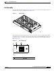
CPU Switch Module Ports, LEDs, and Switches
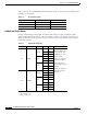
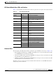
Table 1-3 lists the LEDs on the CPU switch module faceplate with a description of the status indication.
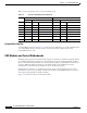
Connector Ports
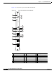
The front panel on the CPU switch module contains three ports with RJ-45 connectors (see Figure 1-11):
• Network Management Ethernet port (NME)—This Ethernet port connects the CPU switch module
to a 10/100BASE-T network management LAN.
• Console port (CON)—This asynchronous EIA/TIA-232 serial port connects a terminal to the CPU
switch module for local administrative access.
• Auxiliary port (AUX)—This asynchronous EIA/TIA-232 serial port connects a modem to the CPU
switch module for remote administrative access.
The RJ-45 connectors on the front panel of the CPU switch module have an extra EMI shield and the
signals going to them are filtered.
Table 1-3 CPU Switch Module LEDs
LED Status Description
STATUS Green IOS is loaded and running.
Yellow Card is in the process of booting.
ACTIVE Green Module is the primary CPU switch
module, otherwise the LED is off.
STANDBY Green Module is in standby mode, otherwise the
LED is off.
ALARM LEDs
CRITICAL Red A system wide critical alarm exists.
MAJOR Yellow A system wide major alarm exists.
MINOR Yellow A system wide minor alarm exists.
HIST Yellow A system wide major or minor alarm has
occurred.
HIST CLR Yellow A system wide major or minor alarm has
occurred.
CUTOFF Red A major or minor alarm exists and the
cutoff button has been pushed.
FDX Green Module is running full-duplex.
Off Module is running half-duplex.
100MBPS Green Module is running at 100 Mbps.
Off Module is running at 10 Mbps.
LINK Green Link is up.
Off Link is down.