
Installation guide

1-8
Cisco ONS 15530 Hardware Installation Guide
OL-7706-01
Chapter 1 Cisco ONS 15530 Overview
Cisco ONS 15530 Chassis
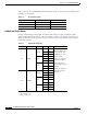
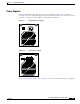
Table 1-1 lists the fan assembly LED status describing the alarm reports for the fan assembly. The fan
assembly is hot-swappable.
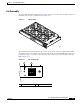
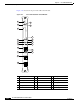
Audible and Visible Alarms
The Cisco ONS 15530 provides audible and visible alarm status to the Telco central office alarm
equipment through hardware located on the fan assembly (see Figure 1-8). Software determines the
alarm condition and sets the appropriate relays for critical, major, or minor alarms. Table 1-2 lists the
terminal block pinouts.
Table 1-1 Fan Assembly Status
Fan Failure LED Status
None Green Normal
One Yellow Minor
Two or more Red Major
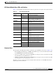
Table 1-2 Terminal Block Pinouts
Connector Alarm Type Level Pin Contact Notes
P1 Visible
Critical
1C
1
1. C = center
Each type and level of
alarm is signaled by a
contact closure of C
to NO and an open
from C to NC.
Voltage at contacts is
limited to 48 VDC.
Switched current /
load is limited to 1-A
resistive.
Alarms are signaled
when the chassis is
unpowered.
2NC
2
2. NC = normally closed
3NO
3
3. NO = normally open
Major
4C
5NC
6NO
Minor
7C
8NC
9NO
P2 Audible
Critical
1C
2NC
3NO
Major
4C
5NC
6NO
Minor
7C
8NC
9NO