
Installation guide

A-14
Cisco ONS 15530 Hardware Installation Guide
OL-7706-01
Appendix A Specifications
2.5-Gbps ITU Trunk Card Specifications
SDI Jitter Performance
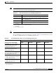
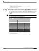
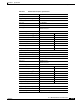
SDI video signal is compliant to the ANSI/SMPTE 259M-1997 standard. Table A-21 lists the SDI jitter
performance values for the 8-port multi-service muxponder.
If your configuration uses an on-board system clock for trunk multiplexing, the client OC-3 wander
generation may exceed the GR-253 specification of less than 60 ns MTIE (maximum time interval error)
on greater than 10-second intervals and 20 ns MTIE on less than 1-second intervals. Because the MTIE
can reach 100 ns across all observation intervals with this configuration, we do not recommend using the
OC-3 transport for deriving the network clock. Other applications operate normally. If needed, the trunk
multiplex clock can be configured to use one of the client OC-3 receive clocks. In this configuration, the
OC-3 wander generation is fully compliant to GR-253 specification.
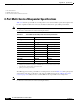
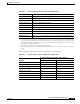
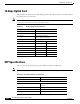
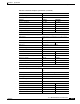
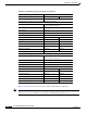
2.5-Gbps ITU Trunk Card Specifications
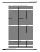
Table A-22 lists the 2.5-Gbps ITU trunk card receiver and transmitter specifications. Optical loss due to
splitter modules and connectors should be included in the optical budget calculation.
Note The optical specifications described in this section are only for the individual components and should
not be used to characterize the entire network performance.
Table A-21 SDI Jitter Performance Values for the 8-Port Multi-Service Muxponder
Hp Filter 10 Hz 1 kHz 10 kHz 100 kHz
Jitter Generation (p-p) 0.5 UI
1
1. Maximum jitter generation is below SMPTE 259 M specification of 0.2 UI (0.74 ns) with the exception of low-frequency
timing jitter. However, a purely digital system will operate correctly with significant amounts of low-frequency jitter as also
indicated in Annex B of SMPTE 259M of the Timing Jitter Specification.
0.06 UI 0.06 UI 0.06 UI
UI / Time 1.85 ns 220 ps 220 ps 220 ps
Table A-22 2.5-Gbps ITU Trunk Card Optical Specifications
Description
Specification
Fiber type SM
1
9 micron
1. SM = single mode.
Connector MU
Receiver Minimum Maximum
OSNR
2
,
3
19 dB
Receive sensitivity
3
–28 dBm
Receive overload –8 dBm
Input wavelength 1260 nm 1580 nm
Transmitter Minimum Maximum
Transmitter power 5 dBm 10 dBm
Dispersion tolerance 3200 ps/nm
4