
Installation guide


A-7
Cisco ONS 15530 Hardware Installation Guide
OL-7706-01
Appendix A Specifications
Transponder Line Card Specifications
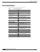
Transponder Line Card Specifications
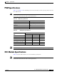
Table A-9 lists the transponder line card receiver and transmitter specifications for the client side lasers.
Note The optical specifications described in this section are only for the individual components and should
not be used to characterize the entire network performance.
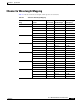
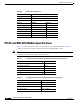
Table A-10 lists the transponder line card receiver and transmitter specifications for the trunk side lasers.
Note Optical loss due to splitter modules and connectors should be included in the optical budget calculation.
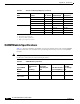
Table A-9 Client Side Optical Specifications
Description Specification
Fiber type SM
1
9 micron
1. SM = single mode
Connector SC
Receiver SM Minimum SM Maximum MM
2
Minimum
2. MM = multimode
MM Maximum
Receive sensitivity –19 dBm –25 dBm
Receive overload –1.5 dBm –8 dBm
Input wavelength 1249 to 1600 nm
3
3. nm = nanometers
1249 to 1600 nm
Optical reflectance –27 dB
4
4. dB = decibels
Receiver fiber pigtail MM 50 micron MM 62.5 micron
Transmitter SM Minimum SM Maximum MM
5
Minimum
5. MM = multimode
MM Maximum
Output wavelength 1260 to 1360 nm 1260 to 1360 nm
Transmitter power –5 dBm 0 dBm –5 dBm 0 dBm
Table A-10 Trunk Side Optical Specifications
Description Specification
Fiber type SM 9 micron
Connector MU
Receiver Minimum Maximum
OSNR
1
,
2
19 dB
Receive sensitivity
2
–28 dBm
Receive overload –8 dBm
Input wavelength 1260 nm 1580 nm