
Installation guide

3-32
Cisco ONS 15530 Hardware Installation Guide
OL-7706-01
Chapter 3 Connecting the Cisco ONS 15530
Connecting the WB-VOA and PB-OE Modules
PB-OE on the Trunk to Equalizing Add Channel Power to Pass Through Power
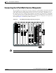
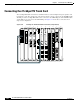
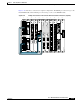
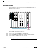
The PB-OE provides per-band attenuation on the trunk. Figure 3-29 shows an example of an unprotected
configuration of a PB-OE module cabled on the trunk. In this example, the PB-OE is the top module in
slot 9, and the WB-VOA is the bottom module in slot 9.
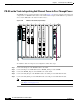
Figure 3-29 PB-OE on the Trunk (Unprotected)
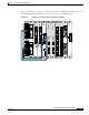
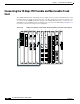
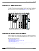
To install the cables in an unprotected configuration, follow these steps:
Step 1 Connect the OUT port of the PB-OE module to the trunk.
Step 2 Connect the IN port of the PB-OE module to TRUNK_OUT port of the OADM.
Step 3 Connect the TRUNK_IN port of the OADM to the outside trunk.
Step 4 Connect the UPG_IN port of the PB-OE module to the OUT port of the WB-VOA module.
Step 5 Connect the UPG_OUT port of the PB-OE module to the IN port of the WB-VOA module.
Note The IN ports on the OADM module (slot 0) are on the left, the OUT ports are on the right.
(See Figure 1-16 on page 1-21).
91706
STATUS
TX
RX
T
X
R
X
15530-OSCM
STATUS
RESET
ACTIVE
STANDBY
COMPACT
FLASH
CIRTICAL
MAJOR
AUX
NME
FDX
100MBPS
LINK
CON
CUTOFF
HIST
CLR
CUTOFF
HIST
MINOR
15530-CPU
A
L
A
R
M
S
STATUS
RESET
ACTIVE
STANDBY
COMPACT
FLASH
CIRTICAL
MAJOR
AUX
NME
FDX
100MBPS
LINK
CON
CUTOFF
HIST
CLR
CUTOFF
HIST
MINOR
15530-CPU
A
L
A
R
M
S
PM2 PM1 STA
15500-PEQ-02EF
IN OUT UPG IN UPG OUT
10
STATUS
T
X
T
X
T
X
R
X
R
X
R
X
T
X
R
X
STATUS
T
X
T
X
T
X
R
X
R
X
R
X
T
X
R
X
2345678910
PM1
PM2
STA
15500-VOA-0200
IN1 OUT1 IN2 OUT2