
Installation guide

3-30
Cisco ONS 15530 Hardware Installation Guide
OL-7706-01
Chapter 3 Connecting the Cisco ONS 15530
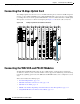
Connecting the WB-VOA and PB-OE Modules
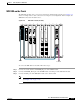
WB-VOA Attenuation on the Receive Side
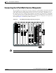
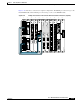
The WB-VOA module can be connected on the receive side to attenuate the signal. Figure 3-27 shows
an example of WB-VOA attenuation on the receive side in an unprotected configuration. In this example,
the WB-VOA is the top module in slot 9.
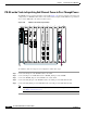
Figure 3-27 WB-VOA Attenuation on the Receive Side (Unprotected)
To install the cables, follow these steps:
Step 1 Connect the IN port of the WB-VOA module to the channel OUT port of the OADM.
Step 2 Connect the OUT port of the WB-VOA module to the RX port of the transponder.
Step 3 Connect the TX port of the transponder to the channel IN port of the OADM.
Note The IN ports on the OADM module (slot 0) are on the left, the OUT ports are on the right.
(See Figure 1-16 on page 1-21).
PM1
PM2
STA
15500-VOA-0200
IN1 OUT1 IN2 OUT2
91703
STATUS
TX
RX
T
X
R
X
15530-OSCM
STATUS
RESET
ACTIVE
STANDBY
COMPACT
FLASH
CIRTICAL
MAJOR
AUX
NME
FDX
100MBPS
LINK
CON
CUTOFF
HIST
CLR
CUTOFF
HIST
MINOR
15530-CPU
A
L
A
R
M
S
STATUS
RESET
ACTIVE
STANDBY
COMPACT
FLASH
CIRTICAL
MAJOR
AUX
NME
FDX
100MBPS
LINK
CON
CUTOFF
HIST
CLR
CUTOFF
HIST
MINOR
15530-CPU
A
L
A
R
M
S
PM2 PM1 STA
15500-PEQ-02EF
IN OUT UPG IN UPG OUT
10
STATUS
T
X
T
X
T
X
R
X
R
X
R
X
T
X
R
X
STATUS
T
X
T
X
T
X
R
X
R
X
R
X
T
X
R
X
2345678910