
Datasheet


Table Of Contents
- Cisco ONS 15454 SDH Reference Manual
- Contents
- About this Manual
- Shelf and FMEC Hardware
- 1.1 Overview
- 1.2 Front Door
- 1.3 Front Mount Electrical Connection
- 1.4 E1-75/120 Conversion Panel
- 1.5 Coaxial Cable
- 1.6 Twisted-Pair Balanced Cable
- 1.7 Ethernet Cables
- 1.8 Cable Routing and Management
- 1.9 Fiber Management
- 1.10 Fan-Tray Assembly
- 1.11 Power and Ground Description
- 1.12 Alarm, Timing, LAN, and Craft Pin Connections
- 1.13 Cards and Slots
- 1.14 Software and Hardware Compatibility
- Common Control Cards
- Electrical Cards
- 3.1 Electrical Card Overview
- 3.2 E1-N-14 Card
- 3.3 E1-42 Card
- 3.4 E3-12 Card
- 3.5 DS3i-N-12 Card
- 3.6 STM1E-12 Card
- 3.7 FILLER Card
- 3.8 FMEC-E1 Card
- 3.9 FMEC-DS1/E1 Card
- 3.10 FMEC E1-120NP Card
- 3.11 FMEC E1-120PROA Card
- 3.12 FMEC E1-120PROB Card
- 3.13 E1-75/120 Impedance Conversion Panel
- 3.14 FMEC-E3/DS3 Card
- 3.15 FMEC STM1E 1:1 Card
- 3.16 BLANK-FMEC Faceplate
- 3.17 MIC-A/P FMEC
- 3.18 MIC-C/T/P FMEC
- Optical Cards
- 4.1 Optical Card Overview
- 4.2 OC3 IR 4/STM1 SH 1310 Card
- 4.3 OC3 IR/STM1 SH 1310-8 Card
- 4.4 OC12 IR/STM4 SH 1310 Card
- 4.5 OC12 LR/STM4 LH 1310 Card
- 4.6 OC12 LR/STM4 LH 1550 Card
- 4.7 OC12 IR/STM4 SH 1310-4 Card
- 4.8 OC48 IR/STM16 SH AS 1310 Card
- 4.9 OC48 LR/STM16 LH AS 1550 Card
- 4.10 OC48 ELR/STM16 EH 100 GHz Cards
- 4.11 OC192 SR/STM64 IO 1310 Card
- 4.12 OC192 IR/STM64 SH 1550 Card
- 4.13 OC192 LR/STM64 LH 1550 Card
- 4.14 OC192 LR/STM64 LH ITU 15xx.xx Card
- 4.15 15454_MRC-12 Multirate Card
- 4.16 OC192SR1/STM64IO Short Reach and OC192/STM64 Any Reach Cards
- 4.17 SFPs and XFPs
- Ethernet Cards
- Storage Access Networking Cards
- Card Protection
- Cisco Transport Controller Operation
- Security
- Timing
- Circuits and Tunnels
- 11.1 Overview
- 11.2 Circuit Properties
- 11.3 Cross-Connect Card Bandwidth
- 11.4 DCC Tunnels
- 11.5 Multiple Destinations for Unidirectional Circuits
- 11.6 Monitor Circuits
- 11.7 SNCP Circuits
- 11.8 MS-SPRing Protection Channel Access Circuits
- 11.9 MS-SPRing VC4 Squelch Table
- 11.10 Section and Path Trace
- 11.11 Path Signal Label, C2 Byte
- 11.12 Automatic Circuit Routing
- 11.13 Manual Circuit Routing
- 11.14 Constraint-Based Circuit Routing
- 11.15 Virtual Concatenated Circuits
- 11.16 Bridge and Roll
- 11.17 Merged Circuits
- 11.18 Reconfigured Circuits
- 11.19 Server Trails
- SDH Topologies and Upgrades
- Management Network Connectivity
- 13.1 IP Networking Overview
- 13.2 IP Addressing Scenarios
- 13.2.1 Scenario 1: CTC and ONS 15454 SDH Nodes on Same Subnet
- 13.2.2 Scenario 2: CTC and ONS 15454 SDH Nodes Connected to a Router
- 13.2.3 Scenario 3: Using Proxy ARP to Enable an ONS 15454 SDH Gateway
- 13.2.4 Scenario 4: Default Gateway on CTC Computer
- 13.2.5 Scenario 5: Using Static Routes to Connect to LANs
- 13.2.6 Scenario 6: Using OSPF
- 13.2.7 Scenario 7: Provisioning the ONS 15454 SDH Proxy Server
- 13.2.8 Scenario 8: Dual GNEs on a Subnet
- 13.2.9 Scenario 9: IP Addressing with Secure Mode Enabled
- 13.3 Provisionable Patchcords
- 13.4 Routing Table
- 13.5 External Firewalls
- 13.6 Open GNE
- 13.7 TCP/IP and OSI Networking
- 13.7.1 Point-to-Point Protocol
- 13.7.2 Link Access Protocol on the D Channel
- 13.7.3 OSI Connectionless Network Service
- 13.7.4 OSI Routing
- 13.7.5 TARP
- 13.7.6 TCP/IP and OSI Mediation
- 13.7.7 OSI Virtual Routers
- 13.7.8 IP-over-CLNS Tunnels
- 13.7.9 OSI/IP Networking Scenarios
- 13.7.9.1 OSI/IP Scenario 1: IP OSS, IP DCN, ONS GNE, IP DCC, and ONS ENE
- 13.7.9.2 OSI/IP Scenario 2: IP OSS, IP DCN, ONS GNE, OSI DCC, and Other Vendor ENE
- 13.7.9.3 OSI/IP Scenario 3: IP OSS, IP DCN, Other Vendor GNE, OSI DCC, and ONS ENE
- 13.7.9.4 OSI/IP Scenario 4: Multiple ONS DCC Areas
- 13.7.9.5 OSI/IP Scenario 5: GNE Without an OSI DCC Connection
- 13.7.9.6 OSI/IP Scenario 6: IP OSS, OSI DCN, ONS GNE, OSI DCC, and Other Vendor ENE
- 13.7.9.7 OSI/IP Scenario 7: OSI OSS, OSI DCN, Other Vendor GNE, OSI DCC, and ONS NEs
- 13.7.9.8 OSI/IP Scenario 8: OSI OSS, OSI DCN, ONS GNE, OSI DCC, and Other Vendor NEs
- 13.7.10 Provisioning OSI in CTC
- Alarm Monitoring and Management
- 14.1 Overview
- 14.2 LCD Alarm Counts
- 14.3 Alarm Information
- 14.4 Alarm Severities
- 14.5 Alarm Profiles
- 14.6 Alarm Suppression
- 14.7 External Alarms and Controls
- Performance Monitoring
- 15.1 Threshold Performance Monitoring
- 15.2 Intermediate-Path Performance Monitoring
- 15.3 Pointer Justification Count Performance Monitoring
- 15.4 Performance Monitoring Parameter Definitions
- 15.5 Performance Monitoring for Electrical Cards
- 15.6 Performance Monitoring for Ethernet Cards
- 15.6.1 E-Series Ethernet Card Performance Monitoring Parameters
- 15.6.2 G-Series Ethernet Card Performance Monitoring Parameters
- 15.6.3 ML-Series Ethernet Card Performance Monitoring Parameters
- 15.6.4 CE-Series Ethernet Card Performance Monitoring Parameters
- 15.6.4.1 CE-Series Ether Ports Statistics Parameters
- 15.6.4.2 CE-Series Card Ether Ports Utilization Parameters
- 15.6.4.3 CE-Series Card Ether Ports History Parameters
- 15.6.4.4 CE-Series POS Ports Statistics Parameters
- 15.6.4.5 CE-Series Card POS Ports Utilization Parameters
- 15.6.4.6 CE-Series Card Ether Ports History Parameters
- 15.7 Performance Monitoring for Optical Cards
- 15.8 Performance Monitoring for the Fiber Channel Card
- SNMP
- 16.1 SNMP Overview
- 16.2 Basic SNMP Components
- 16.3 SNMP External Interface Requirement
- 16.4 SNMP Version Support
- 16.5 SNMP Message Types
- 16.6 SNMP Management Information Bases
- 16.7 SNMP Trap Content
- 16.8 SNMP Community Names
- 16.9 Proxy Over Firewalls
- 16.10 Remote Monitoring
- Hardware Specifications
- A.1 Shelf Specifications
- A.2 SFP and XFP Specifications
- A.3 General Card Specifications
- A.4 Common Control Card Specifications
- A.5 Electrical Card and FMEC Specifications
- A.5.1 E1-N-14 Card Specifications
- A.5.2 E1-42 Card Specifications
- A.5.3 E3-12 Card Specifications
- A.5.4 DS3i-N-12 Card Specifications
- A.5.5 STM1E-12 Card Specifications
- A.5.6 FILLER Card
- A.5.7 FMEC-E1 Specifications
- A.5.8 FMEC-DS1/E1 Specifications
- A.5.9 FMEC E1-120NP Specifications
- A.5.10 FMEC E1-120PROA Specifications
- A.5.11 FMEC E1-120PROB Specifications
- A.5.12 E1-75/120 Impedance Conversion Panel Specifications
- A.5.13 FMEC-E3/DS3 Specifications
- A.5.14 FMEC STM1E 1:1 Specifications
- A.5.15 BLANK-FMEC Specifications
- A.5.16 MIC-A/P Specifications
- A.5.17 MIC-C/T/P Specifications
- A.6 Optical Card Specifications
- A.6.1 OC3 IR 4/STM1 SH 1310 Card Specifications
- A.6.2 OC3 IR/STM1 SH 1310-8 Card Specifications
- A.6.3 OC12 IR/STM4 SH 1310 Card Specifications
- A.6.4 OC12 LR/STM4 LH 1310 Card Specifications
- A.6.5 OC12 LR/STM4 LH 1550 Card Specifications
- A.6.6 OC12 IR/STM4 SH 1310-4 Card Specifications
- A.6.7 OC48 IR/STM16 SH AS 1310 Card Specifications
- A.6.8 OC48 LR/STM16 LH AS 1550 Card Specifications
- A.6.9 OC48 ELR/STM16 EH 100 GHz Card Specifications
- A.6.10 OC192 SR/STM64 IO 1310 Card Specifications
- A.6.11 OC192 IR/STM64 SH 1550 Card Specifications
- A.6.12 OC192 LR/STM64 LH 1550 Card Specifications
- A.6.13 OC192 LR/STM64 LH ITU 15xx.xx Card Specifications
- A.6.14 15454_MRC-12 Card Specifications
- A.6.15 OC192SR1/STM64IO Short Reach Card Specifications
- A.6.16 OC192/STM64 Any Reach Card Specifications
- A.7 Ethernet Card Specifications
- A.8 Storage Access Networking Card Specifications
- Administrative and Service States
- Network Element Defaults
- C.1 Network Element Defaults Description
- C.2 Card Default Settings
- C.2.1 Configuration Defaults
- C.2.2 Threshold Defaults
- C.2.3 Defaults by Card
- C.2.3.1 E1-N-14 Card Default Settings
- C.2.3.2 E1-42 Card Default Settings
- C.2.3.3 E3-12 Card Default Settings
- C.2.3.4 DS3i-N-12 Card Default Settings
- C.2.3.5 STM1E-12 Card Default Settings
- C.2.3.6 Ethernet Card Default Settings
- C.2.3.7 STM-1 Card Default Settings
- C.2.3.8 STM1-8 Card Default Settings
- C.2.3.9 STM-4 Card Default Settings
- C.2.3.10 STM4-4 Card Default Settings
- C.2.3.11 STM-16 Card Default Settings
- C.2.3.12 STM-64 Card Default Settings
- C.2.3.13 STM64-XFP Default Settings
- C.2.3.14 MRC-12 Card Default Settings
- C.2.3.15 FC_MR-4 Card Default Settings
- C.3 Node Default Settings
- C.4 CTC Default Settings
- Index
15-14
Cisco ONS 15454 SDH Reference Manual, R7.0
October 2008
Chapter 15 Performance Monitoring
15.5 Performance Monitoring for Electrical Cards
15.5 Performance Monitoring for Electrical Cards
The following sections define performance monitoring parameters for the E1-N-14, E1-42, E3-12, and
DS3i-N-12 electrical cards.
15.5.1 E1-N-14 Card and E1-42 Card Performance Monitoring Parameters
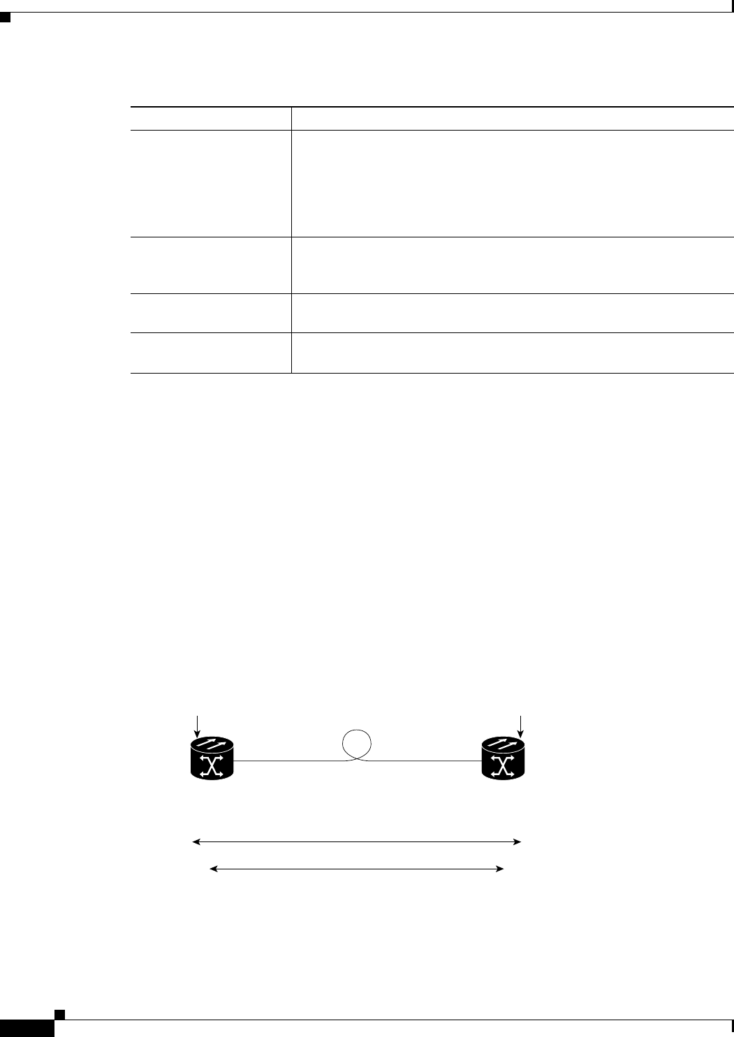
Figure 15-2 shows the signal types that support near-end and far-end PM parameters for the E1-N-14
card and the E1-42 card.
Figure 15-2 Monitored Signal Types for the E1-N-14 Card and E1-42 Card
Figure 15-3 shows where overhead bytes detected on the application-specific integrated circuits (ASICs)
produce performance monitoring parameters for the E1-N-14 card.
UASP-P Unavailable Second Path (UASP-P) is a count of one-second intervals
when the DS-3 path is unavailable. A DS3 path becomes unavailable when
ten consecutive SESP-Ps occur. The ten SESP-Ps are included in
unavailable time. After the DS-3 path becomes unavailable, it becomes
available when ten consecutive seconds with no SESP-Ps occur. The ten
seconds with no SESP-Ps are excluded from unavailable time.
UAS-SM Section Monitoring Unavailable Seconds (UAS-SM) indicates the
unavailable seconds recorded in the OTN section during the PM time
interval.
UNC-WORDS The number of uncorrectable words detected in the DWDM trunk line
during the PM time interval.
VPC A count of received packets that contain non-errored data code groups that
have start and end delimiters.
1. 4-fiber MS-SPRing is not supported on the STM-4 and STM4 SH 1310-4 cards; therefore, the MS-PSC-S and MS-PSC-R PM
parameters do not increment.
Table 15-3 Performance Monitoring Parameters (continued)
Parameter Definition
71101
ONS 15454
SDH
E1 STM16
Fiber
Near End
E1 Signal
CRC4 Framing Path PMs Near + Far End Supported
ONS 15454
SDH
E1STM16
Far End
E1 Signal
VC-12 Low-Order Path PMs Near End Supported