
Datasheet


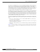


Table Of Contents
- Cisco ONS 15454 SDH Reference Manual
- Contents
- About this Manual
- Shelf and FMEC Hardware
- 1.1 Overview
- 1.2 Front Door
- 1.3 Front Mount Electrical Connection
- 1.4 E1-75/120 Conversion Panel
- 1.5 Coaxial Cable
- 1.6 Twisted-Pair Balanced Cable
- 1.7 Ethernet Cables
- 1.8 Cable Routing and Management
- 1.9 Fiber Management
- 1.10 Fan-Tray Assembly
- 1.11 Power and Ground Description
- 1.12 Alarm, Timing, LAN, and Craft Pin Connections
- 1.13 Cards and Slots
- 1.14 Software and Hardware Compatibility
- Common Control Cards
- Electrical Cards
- 3.1 Electrical Card Overview
- 3.2 E1-N-14 Card
- 3.3 E1-42 Card
- 3.4 E3-12 Card
- 3.5 DS3i-N-12 Card
- 3.6 STM1E-12 Card
- 3.7 FILLER Card
- 3.8 FMEC-E1 Card
- 3.9 FMEC-DS1/E1 Card
- 3.10 FMEC E1-120NP Card
- 3.11 FMEC E1-120PROA Card
- 3.12 FMEC E1-120PROB Card
- 3.13 E1-75/120 Impedance Conversion Panel
- 3.14 FMEC-E3/DS3 Card
- 3.15 FMEC STM1E 1:1 Card
- 3.16 BLANK-FMEC Faceplate
- 3.17 MIC-A/P FMEC
- 3.18 MIC-C/T/P FMEC
- Optical Cards
- 4.1 Optical Card Overview
- 4.2 OC3 IR 4/STM1 SH 1310 Card
- 4.3 OC3 IR/STM1 SH 1310-8 Card
- 4.4 OC12 IR/STM4 SH 1310 Card
- 4.5 OC12 LR/STM4 LH 1310 Card
- 4.6 OC12 LR/STM4 LH 1550 Card
- 4.7 OC12 IR/STM4 SH 1310-4 Card
- 4.8 OC48 IR/STM16 SH AS 1310 Card
- 4.9 OC48 LR/STM16 LH AS 1550 Card
- 4.10 OC48 ELR/STM16 EH 100 GHz Cards
- 4.11 OC192 SR/STM64 IO 1310 Card
- 4.12 OC192 IR/STM64 SH 1550 Card
- 4.13 OC192 LR/STM64 LH 1550 Card
- 4.14 OC192 LR/STM64 LH ITU 15xx.xx Card
- 4.15 15454_MRC-12 Multirate Card
- 4.16 OC192SR1/STM64IO Short Reach and OC192/STM64 Any Reach Cards
- 4.17 SFPs and XFPs
- Ethernet Cards
- Storage Access Networking Cards
- Card Protection
- Cisco Transport Controller Operation
- Security
- Timing
- Circuits and Tunnels
- 11.1 Overview
- 11.2 Circuit Properties
- 11.3 Cross-Connect Card Bandwidth
- 11.4 DCC Tunnels
- 11.5 Multiple Destinations for Unidirectional Circuits
- 11.6 Monitor Circuits
- 11.7 SNCP Circuits
- 11.8 MS-SPRing Protection Channel Access Circuits
- 11.9 MS-SPRing VC4 Squelch Table
- 11.10 Section and Path Trace
- 11.11 Path Signal Label, C2 Byte
- 11.12 Automatic Circuit Routing
- 11.13 Manual Circuit Routing
- 11.14 Constraint-Based Circuit Routing
- 11.15 Virtual Concatenated Circuits
- 11.16 Bridge and Roll
- 11.17 Merged Circuits
- 11.18 Reconfigured Circuits
- 11.19 Server Trails
- SDH Topologies and Upgrades
- Management Network Connectivity
- 13.1 IP Networking Overview
- 13.2 IP Addressing Scenarios
- 13.2.1 Scenario 1: CTC and ONS 15454 SDH Nodes on Same Subnet
- 13.2.2 Scenario 2: CTC and ONS 15454 SDH Nodes Connected to a Router
- 13.2.3 Scenario 3: Using Proxy ARP to Enable an ONS 15454 SDH Gateway
- 13.2.4 Scenario 4: Default Gateway on CTC Computer
- 13.2.5 Scenario 5: Using Static Routes to Connect to LANs
- 13.2.6 Scenario 6: Using OSPF
- 13.2.7 Scenario 7: Provisioning the ONS 15454 SDH Proxy Server
- 13.2.8 Scenario 8: Dual GNEs on a Subnet
- 13.2.9 Scenario 9: IP Addressing with Secure Mode Enabled
- 13.3 Provisionable Patchcords
- 13.4 Routing Table
- 13.5 External Firewalls
- 13.6 Open GNE
- 13.7 TCP/IP and OSI Networking
- 13.7.1 Point-to-Point Protocol
- 13.7.2 Link Access Protocol on the D Channel
- 13.7.3 OSI Connectionless Network Service
- 13.7.4 OSI Routing
- 13.7.5 TARP
- 13.7.6 TCP/IP and OSI Mediation
- 13.7.7 OSI Virtual Routers
- 13.7.8 IP-over-CLNS Tunnels
- 13.7.9 OSI/IP Networking Scenarios
- 13.7.9.1 OSI/IP Scenario 1: IP OSS, IP DCN, ONS GNE, IP DCC, and ONS ENE
- 13.7.9.2 OSI/IP Scenario 2: IP OSS, IP DCN, ONS GNE, OSI DCC, and Other Vendor ENE
- 13.7.9.3 OSI/IP Scenario 3: IP OSS, IP DCN, Other Vendor GNE, OSI DCC, and ONS ENE
- 13.7.9.4 OSI/IP Scenario 4: Multiple ONS DCC Areas
- 13.7.9.5 OSI/IP Scenario 5: GNE Without an OSI DCC Connection
- 13.7.9.6 OSI/IP Scenario 6: IP OSS, OSI DCN, ONS GNE, OSI DCC, and Other Vendor ENE
- 13.7.9.7 OSI/IP Scenario 7: OSI OSS, OSI DCN, Other Vendor GNE, OSI DCC, and ONS NEs
- 13.7.9.8 OSI/IP Scenario 8: OSI OSS, OSI DCN, ONS GNE, OSI DCC, and Other Vendor NEs
- 13.7.10 Provisioning OSI in CTC
- Alarm Monitoring and Management
- 14.1 Overview
- 14.2 LCD Alarm Counts
- 14.3 Alarm Information
- 14.4 Alarm Severities
- 14.5 Alarm Profiles
- 14.6 Alarm Suppression
- 14.7 External Alarms and Controls
- Performance Monitoring
- 15.1 Threshold Performance Monitoring
- 15.2 Intermediate-Path Performance Monitoring
- 15.3 Pointer Justification Count Performance Monitoring
- 15.4 Performance Monitoring Parameter Definitions
- 15.5 Performance Monitoring for Electrical Cards
- 15.6 Performance Monitoring for Ethernet Cards
- 15.6.1 E-Series Ethernet Card Performance Monitoring Parameters
- 15.6.2 G-Series Ethernet Card Performance Monitoring Parameters
- 15.6.3 ML-Series Ethernet Card Performance Monitoring Parameters
- 15.6.4 CE-Series Ethernet Card Performance Monitoring Parameters
- 15.6.4.1 CE-Series Ether Ports Statistics Parameters
- 15.6.4.2 CE-Series Card Ether Ports Utilization Parameters
- 15.6.4.3 CE-Series Card Ether Ports History Parameters
- 15.6.4.4 CE-Series POS Ports Statistics Parameters
- 15.6.4.5 CE-Series Card POS Ports Utilization Parameters
- 15.6.4.6 CE-Series Card Ether Ports History Parameters
- 15.7 Performance Monitoring for Optical Cards
- 15.8 Performance Monitoring for the Fiber Channel Card
- SNMP
- 16.1 SNMP Overview
- 16.2 Basic SNMP Components
- 16.3 SNMP External Interface Requirement
- 16.4 SNMP Version Support
- 16.5 SNMP Message Types
- 16.6 SNMP Management Information Bases
- 16.7 SNMP Trap Content
- 16.8 SNMP Community Names
- 16.9 Proxy Over Firewalls
- 16.10 Remote Monitoring
- Hardware Specifications
- A.1 Shelf Specifications
- A.2 SFP and XFP Specifications
- A.3 General Card Specifications
- A.4 Common Control Card Specifications
- A.5 Electrical Card and FMEC Specifications
- A.5.1 E1-N-14 Card Specifications
- A.5.2 E1-42 Card Specifications
- A.5.3 E3-12 Card Specifications
- A.5.4 DS3i-N-12 Card Specifications
- A.5.5 STM1E-12 Card Specifications
- A.5.6 FILLER Card
- A.5.7 FMEC-E1 Specifications
- A.5.8 FMEC-DS1/E1 Specifications
- A.5.9 FMEC E1-120NP Specifications
- A.5.10 FMEC E1-120PROA Specifications
- A.5.11 FMEC E1-120PROB Specifications
- A.5.12 E1-75/120 Impedance Conversion Panel Specifications
- A.5.13 FMEC-E3/DS3 Specifications
- A.5.14 FMEC STM1E 1:1 Specifications
- A.5.15 BLANK-FMEC Specifications
- A.5.16 MIC-A/P Specifications
- A.5.17 MIC-C/T/P Specifications
- A.6 Optical Card Specifications
- A.6.1 OC3 IR 4/STM1 SH 1310 Card Specifications
- A.6.2 OC3 IR/STM1 SH 1310-8 Card Specifications
- A.6.3 OC12 IR/STM4 SH 1310 Card Specifications
- A.6.4 OC12 LR/STM4 LH 1310 Card Specifications
- A.6.5 OC12 LR/STM4 LH 1550 Card Specifications
- A.6.6 OC12 IR/STM4 SH 1310-4 Card Specifications
- A.6.7 OC48 IR/STM16 SH AS 1310 Card Specifications
- A.6.8 OC48 LR/STM16 LH AS 1550 Card Specifications
- A.6.9 OC48 ELR/STM16 EH 100 GHz Card Specifications
- A.6.10 OC192 SR/STM64 IO 1310 Card Specifications
- A.6.11 OC192 IR/STM64 SH 1550 Card Specifications
- A.6.12 OC192 LR/STM64 LH 1550 Card Specifications
- A.6.13 OC192 LR/STM64 LH ITU 15xx.xx Card Specifications
- A.6.14 15454_MRC-12 Card Specifications
- A.6.15 OC192SR1/STM64IO Short Reach Card Specifications
- A.6.16 OC192/STM64 Any Reach Card Specifications
- A.7 Ethernet Card Specifications
- A.8 Storage Access Networking Card Specifications
- Administrative and Service States
- Network Element Defaults
- C.1 Network Element Defaults Description
- C.2 Card Default Settings
- C.2.1 Configuration Defaults
- C.2.2 Threshold Defaults
- C.2.3 Defaults by Card
- C.2.3.1 E1-N-14 Card Default Settings
- C.2.3.2 E1-42 Card Default Settings
- C.2.3.3 E3-12 Card Default Settings
- C.2.3.4 DS3i-N-12 Card Default Settings
- C.2.3.5 STM1E-12 Card Default Settings
- C.2.3.6 Ethernet Card Default Settings
- C.2.3.7 STM-1 Card Default Settings
- C.2.3.8 STM1-8 Card Default Settings
- C.2.3.9 STM-4 Card Default Settings
- C.2.3.10 STM4-4 Card Default Settings
- C.2.3.11 STM-16 Card Default Settings
- C.2.3.12 STM-64 Card Default Settings
- C.2.3.13 STM64-XFP Default Settings
- C.2.3.14 MRC-12 Card Default Settings
- C.2.3.15 FC_MR-4 Card Default Settings
- C.3 Node Default Settings
- C.4 CTC Default Settings
- Index

13-28
Cisco ONS 15454 SDH Reference Manual, R7.0
October 2008
Chapter 13 Management Network Connectivity
13.6 Open GNE
To configure an open GNE network, you can provision RS-DCC, MS-DCC, and GCC terminations to
include a far-end, non-ONS node using either the default IP address of 0.0.0.0 or a specified IP address.
You provision a far-end, non-ONS node by checking the “Far End is Foreign” check box during
RS-DCC, MS-DCC, and GCC creation. The default 0.0.0.0 IP address allows the far-end, non-ONS node
to provide the IP address; if you set an IP address other than 0.0.0.0, a link is established only if the
far-end node identifies itself with that IP address, providing an extra level of security.
By default, the proxy server only allows connections to discovered ONS peers and the firewall blocks
all IP traffic between the DCC network and LAN. You can, however, provision proxy tunnels to allow
up to 12 additional destinations for SOCKS version 5 connections to non-ONS nodes. You can also
provision firewall tunnels to allow up to 12 additional destinations for direct IP connectivity between the
DCC network and LAN. Proxy and firewall tunnels include both a source and destination subnet. The
connection must originate within the source subnet and terminate within the destination subnet before
either the SOCKS connection or IP packet flow is allowed.
To set up proxy and firewall subnets in CTC, use the Provisioning > Network > Proxy and Firewalls
subtabs. The availability of proxy and/or firewall tunnels depends on the network access settings of the
node:
• If the node is configured with the proxy server enabled in GNE or ENE mode, you must set up a
proxy tunnel and/or a firewall tunnel.
• If the node is configured with the proxy server enabled in proxy-only mode, you can set up proxy
tunnels. Firewall tunnels are not allowed.
• If the node is configured with the proxy server disabled, neither proxy tunnels or firewall tunnels
are allowed.
Figure 13-18 shows an example of a foreign node connected to the DCC network. Proxy and firewall
tunnels are useful in this example because the GNE would otherwise block IP access between the PC
and the foreign node.