
Datasheet
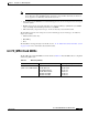


Table Of Contents
- Cisco ONS 15454 SDH Reference Manual
- Contents
- About this Manual
- Shelf and FMEC Hardware
- 1.1 Overview
- 1.2 Front Door
- 1.3 Front Mount Electrical Connection
- 1.4 E1-75/120 Conversion Panel
- 1.5 Coaxial Cable
- 1.6 Twisted-Pair Balanced Cable
- 1.7 Ethernet Cables
- 1.8 Cable Routing and Management
- 1.9 Fiber Management
- 1.10 Fan-Tray Assembly
- 1.11 Power and Ground Description
- 1.12 Alarm, Timing, LAN, and Craft Pin Connections
- 1.13 Cards and Slots
- 1.14 Software and Hardware Compatibility
- Common Control Cards
- Electrical Cards
- 3.1 Electrical Card Overview
- 3.2 E1-N-14 Card
- 3.3 E1-42 Card
- 3.4 E3-12 Card
- 3.5 DS3i-N-12 Card
- 3.6 STM1E-12 Card
- 3.7 FILLER Card
- 3.8 FMEC-E1 Card
- 3.9 FMEC-DS1/E1 Card
- 3.10 FMEC E1-120NP Card
- 3.11 FMEC E1-120PROA Card
- 3.12 FMEC E1-120PROB Card
- 3.13 E1-75/120 Impedance Conversion Panel
- 3.14 FMEC-E3/DS3 Card
- 3.15 FMEC STM1E 1:1 Card
- 3.16 BLANK-FMEC Faceplate
- 3.17 MIC-A/P FMEC
- 3.18 MIC-C/T/P FMEC
- Optical Cards
- 4.1 Optical Card Overview
- 4.2 OC3 IR 4/STM1 SH 1310 Card
- 4.3 OC3 IR/STM1 SH 1310-8 Card
- 4.4 OC12 IR/STM4 SH 1310 Card
- 4.5 OC12 LR/STM4 LH 1310 Card
- 4.6 OC12 LR/STM4 LH 1550 Card
- 4.7 OC12 IR/STM4 SH 1310-4 Card
- 4.8 OC48 IR/STM16 SH AS 1310 Card
- 4.9 OC48 LR/STM16 LH AS 1550 Card
- 4.10 OC48 ELR/STM16 EH 100 GHz Cards
- 4.11 OC192 SR/STM64 IO 1310 Card
- 4.12 OC192 IR/STM64 SH 1550 Card
- 4.13 OC192 LR/STM64 LH 1550 Card
- 4.14 OC192 LR/STM64 LH ITU 15xx.xx Card
- 4.15 15454_MRC-12 Multirate Card
- 4.16 OC192SR1/STM64IO Short Reach and OC192/STM64 Any Reach Cards
- 4.17 SFPs and XFPs
- Ethernet Cards
- Storage Access Networking Cards
- Card Protection
- Cisco Transport Controller Operation
- Security
- Timing
- Circuits and Tunnels
- 11.1 Overview
- 11.2 Circuit Properties
- 11.3 Cross-Connect Card Bandwidth
- 11.4 DCC Tunnels
- 11.5 Multiple Destinations for Unidirectional Circuits
- 11.6 Monitor Circuits
- 11.7 SNCP Circuits
- 11.8 MS-SPRing Protection Channel Access Circuits
- 11.9 MS-SPRing VC4 Squelch Table
- 11.10 Section and Path Trace
- 11.11 Path Signal Label, C2 Byte
- 11.12 Automatic Circuit Routing
- 11.13 Manual Circuit Routing
- 11.14 Constraint-Based Circuit Routing
- 11.15 Virtual Concatenated Circuits
- 11.16 Bridge and Roll
- 11.17 Merged Circuits
- 11.18 Reconfigured Circuits
- 11.19 Server Trails
- SDH Topologies and Upgrades
- Management Network Connectivity
- 13.1 IP Networking Overview
- 13.2 IP Addressing Scenarios
- 13.2.1 Scenario 1: CTC and ONS 15454 SDH Nodes on Same Subnet
- 13.2.2 Scenario 2: CTC and ONS 15454 SDH Nodes Connected to a Router
- 13.2.3 Scenario 3: Using Proxy ARP to Enable an ONS 15454 SDH Gateway
- 13.2.4 Scenario 4: Default Gateway on CTC Computer
- 13.2.5 Scenario 5: Using Static Routes to Connect to LANs
- 13.2.6 Scenario 6: Using OSPF
- 13.2.7 Scenario 7: Provisioning the ONS 15454 SDH Proxy Server
- 13.2.8 Scenario 8: Dual GNEs on a Subnet
- 13.2.9 Scenario 9: IP Addressing with Secure Mode Enabled
- 13.3 Provisionable Patchcords
- 13.4 Routing Table
- 13.5 External Firewalls
- 13.6 Open GNE
- 13.7 TCP/IP and OSI Networking
- 13.7.1 Point-to-Point Protocol
- 13.7.2 Link Access Protocol on the D Channel
- 13.7.3 OSI Connectionless Network Service
- 13.7.4 OSI Routing
- 13.7.5 TARP
- 13.7.6 TCP/IP and OSI Mediation
- 13.7.7 OSI Virtual Routers
- 13.7.8 IP-over-CLNS Tunnels
- 13.7.9 OSI/IP Networking Scenarios
- 13.7.9.1 OSI/IP Scenario 1: IP OSS, IP DCN, ONS GNE, IP DCC, and ONS ENE
- 13.7.9.2 OSI/IP Scenario 2: IP OSS, IP DCN, ONS GNE, OSI DCC, and Other Vendor ENE
- 13.7.9.3 OSI/IP Scenario 3: IP OSS, IP DCN, Other Vendor GNE, OSI DCC, and ONS ENE
- 13.7.9.4 OSI/IP Scenario 4: Multiple ONS DCC Areas
- 13.7.9.5 OSI/IP Scenario 5: GNE Without an OSI DCC Connection
- 13.7.9.6 OSI/IP Scenario 6: IP OSS, OSI DCN, ONS GNE, OSI DCC, and Other Vendor ENE
- 13.7.9.7 OSI/IP Scenario 7: OSI OSS, OSI DCN, Other Vendor GNE, OSI DCC, and ONS NEs
- 13.7.9.8 OSI/IP Scenario 8: OSI OSS, OSI DCN, ONS GNE, OSI DCC, and Other Vendor NEs
- 13.7.10 Provisioning OSI in CTC
- Alarm Monitoring and Management
- 14.1 Overview
- 14.2 LCD Alarm Counts
- 14.3 Alarm Information
- 14.4 Alarm Severities
- 14.5 Alarm Profiles
- 14.6 Alarm Suppression
- 14.7 External Alarms and Controls
- Performance Monitoring
- 15.1 Threshold Performance Monitoring
- 15.2 Intermediate-Path Performance Monitoring
- 15.3 Pointer Justification Count Performance Monitoring
- 15.4 Performance Monitoring Parameter Definitions
- 15.5 Performance Monitoring for Electrical Cards
- 15.6 Performance Monitoring for Ethernet Cards
- 15.6.1 E-Series Ethernet Card Performance Monitoring Parameters
- 15.6.2 G-Series Ethernet Card Performance Monitoring Parameters
- 15.6.3 ML-Series Ethernet Card Performance Monitoring Parameters
- 15.6.4 CE-Series Ethernet Card Performance Monitoring Parameters
- 15.6.4.1 CE-Series Ether Ports Statistics Parameters
- 15.6.4.2 CE-Series Card Ether Ports Utilization Parameters
- 15.6.4.3 CE-Series Card Ether Ports History Parameters
- 15.6.4.4 CE-Series POS Ports Statistics Parameters
- 15.6.4.5 CE-Series Card POS Ports Utilization Parameters
- 15.6.4.6 CE-Series Card Ether Ports History Parameters
- 15.7 Performance Monitoring for Optical Cards
- 15.8 Performance Monitoring for the Fiber Channel Card
- SNMP
- 16.1 SNMP Overview
- 16.2 Basic SNMP Components
- 16.3 SNMP External Interface Requirement
- 16.4 SNMP Version Support
- 16.5 SNMP Message Types
- 16.6 SNMP Management Information Bases
- 16.7 SNMP Trap Content
- 16.8 SNMP Community Names
- 16.9 Proxy Over Firewalls
- 16.10 Remote Monitoring
- Hardware Specifications
- A.1 Shelf Specifications
- A.2 SFP and XFP Specifications
- A.3 General Card Specifications
- A.4 Common Control Card Specifications
- A.5 Electrical Card and FMEC Specifications
- A.5.1 E1-N-14 Card Specifications
- A.5.2 E1-42 Card Specifications
- A.5.3 E3-12 Card Specifications
- A.5.4 DS3i-N-12 Card Specifications
- A.5.5 STM1E-12 Card Specifications
- A.5.6 FILLER Card
- A.5.7 FMEC-E1 Specifications
- A.5.8 FMEC-DS1/E1 Specifications
- A.5.9 FMEC E1-120NP Specifications
- A.5.10 FMEC E1-120PROA Specifications
- A.5.11 FMEC E1-120PROB Specifications
- A.5.12 E1-75/120 Impedance Conversion Panel Specifications
- A.5.13 FMEC-E3/DS3 Specifications
- A.5.14 FMEC STM1E 1:1 Specifications
- A.5.15 BLANK-FMEC Specifications
- A.5.16 MIC-A/P Specifications
- A.5.17 MIC-C/T/P Specifications
- A.6 Optical Card Specifications
- A.6.1 OC3 IR 4/STM1 SH 1310 Card Specifications
- A.6.2 OC3 IR/STM1 SH 1310-8 Card Specifications
- A.6.3 OC12 IR/STM4 SH 1310 Card Specifications
- A.6.4 OC12 LR/STM4 LH 1310 Card Specifications
- A.6.5 OC12 LR/STM4 LH 1550 Card Specifications
- A.6.6 OC12 IR/STM4 SH 1310-4 Card Specifications
- A.6.7 OC48 IR/STM16 SH AS 1310 Card Specifications
- A.6.8 OC48 LR/STM16 LH AS 1550 Card Specifications
- A.6.9 OC48 ELR/STM16 EH 100 GHz Card Specifications
- A.6.10 OC192 SR/STM64 IO 1310 Card Specifications
- A.6.11 OC192 IR/STM64 SH 1550 Card Specifications
- A.6.12 OC192 LR/STM64 LH 1550 Card Specifications
- A.6.13 OC192 LR/STM64 LH ITU 15xx.xx Card Specifications
- A.6.14 15454_MRC-12 Card Specifications
- A.6.15 OC192SR1/STM64IO Short Reach Card Specifications
- A.6.16 OC192/STM64 Any Reach Card Specifications
- A.7 Ethernet Card Specifications
- A.8 Storage Access Networking Card Specifications
- Administrative and Service States
- Network Element Defaults
- C.1 Network Element Defaults Description
- C.2 Card Default Settings
- C.2.1 Configuration Defaults
- C.2.2 Threshold Defaults
- C.2.3 Defaults by Card
- C.2.3.1 E1-N-14 Card Default Settings
- C.2.3.2 E1-42 Card Default Settings
- C.2.3.3 E3-12 Card Default Settings
- C.2.3.4 DS3i-N-12 Card Default Settings
- C.2.3.5 STM1E-12 Card Default Settings
- C.2.3.6 Ethernet Card Default Settings
- C.2.3.7 STM-1 Card Default Settings
- C.2.3.8 STM1-8 Card Default Settings
- C.2.3.9 STM-4 Card Default Settings
- C.2.3.10 STM4-4 Card Default Settings
- C.2.3.11 STM-16 Card Default Settings
- C.2.3.12 STM-64 Card Default Settings
- C.2.3.13 STM64-XFP Default Settings
- C.2.3.14 MRC-12 Card Default Settings
- C.2.3.15 FC_MR-4 Card Default Settings
- C.3 Node Default Settings
- C.4 CTC Default Settings
- Index
7-2
Cisco ONS 15454 SDH Reference Manual, R7.0
October 2008
Chapter 7 Card Protection
7.1.2 1:N Protection
Figure 7-1 ONS 15454 SDH Cards in a 1:1 Protection Configuration
7.1.2 1:N Protection
1:N protection allows a single card to protect several working cards. An E1-N-14 card protects up to four
E1-N-14 cards, and a DS3i-N-12 card protects up to four DS3i-N-12 cards.
Currently, 1:N protection operates only at the E-1, DS-3, and DS-1 levels. The 1:N protect cards must
match the levels of their working cards. For example, an E1-N-14 protects only E1-N-14 cards, and a
DS3i-N-12 protects only DS3i-N-12 cards.
The physical E-1, DS-3, or DS-1 ports on the ONS 15454 SDH FMEC cards use the working card until
the working card fails. When the node detects this failure, the protect card takes over the physical E-1,
DS-3, or DS-1 electrical interfaces through the relays and signal bridging on the backplane. Figure 7-2
shows the ONS 15454 SDH in a 1:N protection configuration. Each side of the shelf assembly has only
one card protecting all of the cards on that side.
83626
1:1 Protection
FMEC
FMEC
FMEC
FMEC
FMEC
MIC-A/P
MIC-T/C/P
FMEC
FMEC
FMEC
FMEC
FMEC
Timing, Comm., and Control
Cross Connect
Cross Connect
Timing, Comm., and Control
Working
Working
Working
(not electric)
Working
(not electric)
Working
Working
Protect
Protect
Working
Working
Protect
Protect
AIC-I (optional)
1 2 3 4 5 6 7 8 9 1011121314151617
18 19 20 21 22 23 24 25 26 27 28 29