
Datasheet


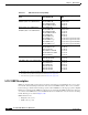
Table Of Contents
- Cisco ONS 15454 SDH Reference Manual
- Contents
- About this Manual
- Shelf and FMEC Hardware
- 1.1 Overview
- 1.2 Front Door
- 1.3 Front Mount Electrical Connection
- 1.4 E1-75/120 Conversion Panel
- 1.5 Coaxial Cable
- 1.6 Twisted-Pair Balanced Cable
- 1.7 Ethernet Cables
- 1.8 Cable Routing and Management
- 1.9 Fiber Management
- 1.10 Fan-Tray Assembly
- 1.11 Power and Ground Description
- 1.12 Alarm, Timing, LAN, and Craft Pin Connections
- 1.13 Cards and Slots
- 1.14 Software and Hardware Compatibility
- Common Control Cards
- Electrical Cards
- 3.1 Electrical Card Overview
- 3.2 E1-N-14 Card
- 3.3 E1-42 Card
- 3.4 E3-12 Card
- 3.5 DS3i-N-12 Card
- 3.6 STM1E-12 Card
- 3.7 FILLER Card
- 3.8 FMEC-E1 Card
- 3.9 FMEC-DS1/E1 Card
- 3.10 FMEC E1-120NP Card
- 3.11 FMEC E1-120PROA Card
- 3.12 FMEC E1-120PROB Card
- 3.13 E1-75/120 Impedance Conversion Panel
- 3.14 FMEC-E3/DS3 Card
- 3.15 FMEC STM1E 1:1 Card
- 3.16 BLANK-FMEC Faceplate
- 3.17 MIC-A/P FMEC
- 3.18 MIC-C/T/P FMEC
- Optical Cards
- 4.1 Optical Card Overview
- 4.2 OC3 IR 4/STM1 SH 1310 Card
- 4.3 OC3 IR/STM1 SH 1310-8 Card
- 4.4 OC12 IR/STM4 SH 1310 Card
- 4.5 OC12 LR/STM4 LH 1310 Card
- 4.6 OC12 LR/STM4 LH 1550 Card
- 4.7 OC12 IR/STM4 SH 1310-4 Card
- 4.8 OC48 IR/STM16 SH AS 1310 Card
- 4.9 OC48 LR/STM16 LH AS 1550 Card
- 4.10 OC48 ELR/STM16 EH 100 GHz Cards
- 4.11 OC192 SR/STM64 IO 1310 Card
- 4.12 OC192 IR/STM64 SH 1550 Card
- 4.13 OC192 LR/STM64 LH 1550 Card
- 4.14 OC192 LR/STM64 LH ITU 15xx.xx Card
- 4.15 15454_MRC-12 Multirate Card
- 4.16 OC192SR1/STM64IO Short Reach and OC192/STM64 Any Reach Cards
- 4.17 SFPs and XFPs
- Ethernet Cards
- Storage Access Networking Cards
- Card Protection
- Cisco Transport Controller Operation
- Security
- Timing
- Circuits and Tunnels
- 11.1 Overview
- 11.2 Circuit Properties
- 11.3 Cross-Connect Card Bandwidth
- 11.4 DCC Tunnels
- 11.5 Multiple Destinations for Unidirectional Circuits
- 11.6 Monitor Circuits
- 11.7 SNCP Circuits
- 11.8 MS-SPRing Protection Channel Access Circuits
- 11.9 MS-SPRing VC4 Squelch Table
- 11.10 Section and Path Trace
- 11.11 Path Signal Label, C2 Byte
- 11.12 Automatic Circuit Routing
- 11.13 Manual Circuit Routing
- 11.14 Constraint-Based Circuit Routing
- 11.15 Virtual Concatenated Circuits
- 11.16 Bridge and Roll
- 11.17 Merged Circuits
- 11.18 Reconfigured Circuits
- 11.19 Server Trails
- SDH Topologies and Upgrades
- Management Network Connectivity
- 13.1 IP Networking Overview
- 13.2 IP Addressing Scenarios
- 13.2.1 Scenario 1: CTC and ONS 15454 SDH Nodes on Same Subnet
- 13.2.2 Scenario 2: CTC and ONS 15454 SDH Nodes Connected to a Router
- 13.2.3 Scenario 3: Using Proxy ARP to Enable an ONS 15454 SDH Gateway
- 13.2.4 Scenario 4: Default Gateway on CTC Computer
- 13.2.5 Scenario 5: Using Static Routes to Connect to LANs
- 13.2.6 Scenario 6: Using OSPF
- 13.2.7 Scenario 7: Provisioning the ONS 15454 SDH Proxy Server
- 13.2.8 Scenario 8: Dual GNEs on a Subnet
- 13.2.9 Scenario 9: IP Addressing with Secure Mode Enabled
- 13.3 Provisionable Patchcords
- 13.4 Routing Table
- 13.5 External Firewalls
- 13.6 Open GNE
- 13.7 TCP/IP and OSI Networking
- 13.7.1 Point-to-Point Protocol
- 13.7.2 Link Access Protocol on the D Channel
- 13.7.3 OSI Connectionless Network Service
- 13.7.4 OSI Routing
- 13.7.5 TARP
- 13.7.6 TCP/IP and OSI Mediation
- 13.7.7 OSI Virtual Routers
- 13.7.8 IP-over-CLNS Tunnels
- 13.7.9 OSI/IP Networking Scenarios
- 13.7.9.1 OSI/IP Scenario 1: IP OSS, IP DCN, ONS GNE, IP DCC, and ONS ENE
- 13.7.9.2 OSI/IP Scenario 2: IP OSS, IP DCN, ONS GNE, OSI DCC, and Other Vendor ENE
- 13.7.9.3 OSI/IP Scenario 3: IP OSS, IP DCN, Other Vendor GNE, OSI DCC, and ONS ENE
- 13.7.9.4 OSI/IP Scenario 4: Multiple ONS DCC Areas
- 13.7.9.5 OSI/IP Scenario 5: GNE Without an OSI DCC Connection
- 13.7.9.6 OSI/IP Scenario 6: IP OSS, OSI DCN, ONS GNE, OSI DCC, and Other Vendor ENE
- 13.7.9.7 OSI/IP Scenario 7: OSI OSS, OSI DCN, Other Vendor GNE, OSI DCC, and ONS NEs
- 13.7.9.8 OSI/IP Scenario 8: OSI OSS, OSI DCN, ONS GNE, OSI DCC, and Other Vendor NEs
- 13.7.10 Provisioning OSI in CTC
- Alarm Monitoring and Management
- 14.1 Overview
- 14.2 LCD Alarm Counts
- 14.3 Alarm Information
- 14.4 Alarm Severities
- 14.5 Alarm Profiles
- 14.6 Alarm Suppression
- 14.7 External Alarms and Controls
- Performance Monitoring
- 15.1 Threshold Performance Monitoring
- 15.2 Intermediate-Path Performance Monitoring
- 15.3 Pointer Justification Count Performance Monitoring
- 15.4 Performance Monitoring Parameter Definitions
- 15.5 Performance Monitoring for Electrical Cards
- 15.6 Performance Monitoring for Ethernet Cards
- 15.6.1 E-Series Ethernet Card Performance Monitoring Parameters
- 15.6.2 G-Series Ethernet Card Performance Monitoring Parameters
- 15.6.3 ML-Series Ethernet Card Performance Monitoring Parameters
- 15.6.4 CE-Series Ethernet Card Performance Monitoring Parameters
- 15.6.4.1 CE-Series Ether Ports Statistics Parameters
- 15.6.4.2 CE-Series Card Ether Ports Utilization Parameters
- 15.6.4.3 CE-Series Card Ether Ports History Parameters
- 15.6.4.4 CE-Series POS Ports Statistics Parameters
- 15.6.4.5 CE-Series Card POS Ports Utilization Parameters
- 15.6.4.6 CE-Series Card Ether Ports History Parameters
- 15.7 Performance Monitoring for Optical Cards
- 15.8 Performance Monitoring for the Fiber Channel Card
- SNMP
- 16.1 SNMP Overview
- 16.2 Basic SNMP Components
- 16.3 SNMP External Interface Requirement
- 16.4 SNMP Version Support
- 16.5 SNMP Message Types
- 16.6 SNMP Management Information Bases
- 16.7 SNMP Trap Content
- 16.8 SNMP Community Names
- 16.9 Proxy Over Firewalls
- 16.10 Remote Monitoring
- Hardware Specifications
- A.1 Shelf Specifications
- A.2 SFP and XFP Specifications
- A.3 General Card Specifications
- A.4 Common Control Card Specifications
- A.5 Electrical Card and FMEC Specifications
- A.5.1 E1-N-14 Card Specifications
- A.5.2 E1-42 Card Specifications
- A.5.3 E3-12 Card Specifications
- A.5.4 DS3i-N-12 Card Specifications
- A.5.5 STM1E-12 Card Specifications
- A.5.6 FILLER Card
- A.5.7 FMEC-E1 Specifications
- A.5.8 FMEC-DS1/E1 Specifications
- A.5.9 FMEC E1-120NP Specifications
- A.5.10 FMEC E1-120PROA Specifications
- A.5.11 FMEC E1-120PROB Specifications
- A.5.12 E1-75/120 Impedance Conversion Panel Specifications
- A.5.13 FMEC-E3/DS3 Specifications
- A.5.14 FMEC STM1E 1:1 Specifications
- A.5.15 BLANK-FMEC Specifications
- A.5.16 MIC-A/P Specifications
- A.5.17 MIC-C/T/P Specifications
- A.6 Optical Card Specifications
- A.6.1 OC3 IR 4/STM1 SH 1310 Card Specifications
- A.6.2 OC3 IR/STM1 SH 1310-8 Card Specifications
- A.6.3 OC12 IR/STM4 SH 1310 Card Specifications
- A.6.4 OC12 LR/STM4 LH 1310 Card Specifications
- A.6.5 OC12 LR/STM4 LH 1550 Card Specifications
- A.6.6 OC12 IR/STM4 SH 1310-4 Card Specifications
- A.6.7 OC48 IR/STM16 SH AS 1310 Card Specifications
- A.6.8 OC48 LR/STM16 LH AS 1550 Card Specifications
- A.6.9 OC48 ELR/STM16 EH 100 GHz Card Specifications
- A.6.10 OC192 SR/STM64 IO 1310 Card Specifications
- A.6.11 OC192 IR/STM64 SH 1550 Card Specifications
- A.6.12 OC192 LR/STM64 LH 1550 Card Specifications
- A.6.13 OC192 LR/STM64 LH ITU 15xx.xx Card Specifications
- A.6.14 15454_MRC-12 Card Specifications
- A.6.15 OC192SR1/STM64IO Short Reach Card Specifications
- A.6.16 OC192/STM64 Any Reach Card Specifications
- A.7 Ethernet Card Specifications
- A.8 Storage Access Networking Card Specifications
- Administrative and Service States
- Network Element Defaults
- C.1 Network Element Defaults Description
- C.2 Card Default Settings
- C.2.1 Configuration Defaults
- C.2.2 Threshold Defaults
- C.2.3 Defaults by Card
- C.2.3.1 E1-N-14 Card Default Settings
- C.2.3.2 E1-42 Card Default Settings
- C.2.3.3 E3-12 Card Default Settings
- C.2.3.4 DS3i-N-12 Card Default Settings
- C.2.3.5 STM1E-12 Card Default Settings
- C.2.3.6 Ethernet Card Default Settings
- C.2.3.7 STM-1 Card Default Settings
- C.2.3.8 STM1-8 Card Default Settings
- C.2.3.9 STM-4 Card Default Settings
- C.2.3.10 STM4-4 Card Default Settings
- C.2.3.11 STM-16 Card Default Settings
- C.2.3.12 STM-64 Card Default Settings
- C.2.3.13 STM64-XFP Default Settings
- C.2.3.14 MRC-12 Card Default Settings
- C.2.3.15 FC_MR-4 Card Default Settings
- C.3 Node Default Settings
- C.4 CTC Default Settings
- Index

5-23
Cisco ONS 15454 SDH Reference Manual, R7.0
October 2008
Chapter 5 Ethernet Cards
5.10 CE-1000-4 Card
• Adding or removing cross connects from the VCG is not service affecting if the associated members
are not in group.
The CE-1000-4 card supports a non link capacity adjustment scheme (no-LCAS). This also makes it
compatible with the ONS 15454 CE-100T-8 and ML-Series cards. The CE-1000-4 card supports VCAT
groups (VCGs) that are fixed and not reconfigurable when no-LCAS is enabled (fixed VCGs).
The following guidelines apply to fixed VCGs:
• Members can be added or removed from VCGs using CTC or TL1.
• Members cannot be put into or out of service unless the force command mode is instantiated.
Note This is possible with CTC as it assumes the force command mode by default. However, to
put members into or out of service using TL1, the force command mode must be set.
• Cross-connects can be added or removed from VCGs using CTC or TL1. This is service affecting
as long as the VCG size (TXCOUNT) is not realigned with the loss of connections.
The CE-1000-4 card supports VCAT differential delay and provides these associated features:
• Supports a maximum VCG differential delay of 122 ms in each direction.
• Supports all protection schemes (path protection, two-fiber BLSR, four-fiber BLSR) on VCAT
circuits that are split-fiber routed.
• Supports two-fiber BLSR on VCAT circuits that are common-fiber routed.
• Differential delay compensation is automatically enabled on VCAT circuits that are diverse (split
fiber) routed, and disabled on VCAT circuits that are common fiber routed.
Figure 5-9 shows the CE-1000-4 card faceplate and block diagram.