
Specifications


4-87
Cisco ONS 15454 Troubleshooting and Maintenance Guide
November 2001
Chapter 4 Card Reference
OC48 ELR 200 GHz Cards
of inexpensive optical amplifiers (flat gain amplifiers) such as erbium doped fiber amplifiers (EDFAs).
Using co-located amplification, distances up to 200 km can be achieved for a single channel (160 km for
8 channels).
Maximum system reach in filterless applications is 24 dB or approximately 80 km without the use of
optical amplifiers or regenerators. However, system reach also depends on the condition of the facilities,
number of splices and connectors or other performance-affecting factors. The OC48 ELR DWDM cards
feature wavelength stability of +/- 0.25 nm. Each interface contains a transmitter and receiver.
The OC48 ELR DWDM cards are the first in a family of cards meant to support extended long reach
applications in conjunction with optical amplification. Using electro-absorption technology, the OC48
DWDM cards provide a solution at the lower-extended long reach distances.
The OC48 LR 1550 interface features a 1550 nm laser and contains a transmit and receive connector
(labeled) on the card faceplate. The card uses SC connectors and supports 1+1 unidirectional and
bidirectional protection switching.
The OC48 ELR cards detect LOS, LOF, LOP, AIS-L, and RDI-L conditions. See Chapter 1, “Alarm
Troubleshooting” for a description of these conditions. The cards also count section and line BIT errors.
To enable APS, the OC48 ELR cards extract the K1 and K2 bytes from the SONET overhead. The DCC
bytes are forwarded to the TCC+ card; the TCC+ terminates the DCC.
4.28.1 OC48 ELR 200 GHz Card-Level Indicators
The OC48 ELR cards have three card-level LED indicators.
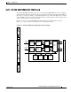
4.28.2 OC48 ELR 200 GHz Port-Level Indicators
You can find the status of the OC48 ELR card ports using the LCD screen on the ONS 15454 fan-tray
assembly. Use the LCD to quickly view the status of any port or card slot; the screen displays the number
and severity of alarms for a given port or slot. See Chapter 1, “Alarm Troubleshooting” for a complete
description of the alarm messages.
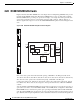
Warning
Invisible laser radiation may be emitted from the end of the unterminated fiber cable or connector.
Do not stare into the beam or view directly with optical instruments. Viewing the laser output with
certain optical instruments (for example, eye loupes, magnifiers, and microscopes) within a
distance of 100 mm may pose an eye hazard. Use of controls or adjustments or performance of
procedures other than those specified may result in hazardous radiation exposure.
Table 4-39 OC48 ELR 200 GHz Card-Level Indicators
Card-Level Indicators Description
Red FAIL LED
The red FAIL LED indicates that the card’s processor is not ready. Replace
the card if the red FAIL LED persists.
Green ACT LED
The green ACT LED indicates that the OC48 ELR card is carrying traffic or
is traffic-ready.
Amber SF LED
The amber SF LED indicates a signal failure or condition such as LOS, LOF
or high BERs on the card’s port. The amber SF LED also illuminates when
the transmit and receive fibers are incorrectly connected. When the fibers are
properly connected, the light turns off.