
Specifications


4-31
Cisco ONS 15454 Troubleshooting and Maintenance Guide
November 2001
Chapter 4 Card Reference
Alarm Interface Controller Card
4.10 Alarm Interface Controller Card
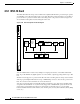
The optional Alarm Interface Controller (AIC) card provides customer-defined alarm input/output (I/O)
and supports local and express orderwire. Figure 4-11 shows the AIC faceplate and a block diagram of
the card. Figure 4-12 on page 4-33 shows the RJ-11 cable.
Figure 4-11 AIC faceplate and block diagram
4.10.1 User-Defined Alarms
The AIC card provides input/output alarm contact closures. You can define up to four external alarms
and four external controls. The physical connections are made using the backplane wire-wrap pins. The
alarms are defined using CTC and TL1. For instructions, see the Cisco ONS 15454 Installation and
Operations Guide.
Each alarm contact has a corresponding LED on the front panel of the AIC that indicates that the status
of the alarm. External alarms (input contacts) are typically used for external sensors such as open doors,
temperature sensors, flood sensors, and other environmental conditions. External controls (output
contacts) are typically used to drive visual or audible devices such as bells and lights, but they can
control other devices such as generators, heaters, and fans.
AIC
Fail
Express orderwire
Local orderwire
Express call
Local call
EEPROM
LED x12
AIC FPGA
SCL links
Relay
Relay
Relay
Relay
Relay
detector
Relay
detector
Relay
detector
Relay
detector
Ringer
Act
Ring
Ring
Input 1
Input 2
Input 3
Input 4
Output 1
Output 2
Output 3
Output 4
61343
FAIL
ACT
INPUT 1
INPUT 2
INPUT 3
INPUT 4
OUTPUT 1
OUTPUT 2
OUTPUT 3
OUTPUT 4
RING
CALL
LOCAL OW
RING
CALL
EXPRESS OW
CONTACT
STATUS
AIC