
Specifications


4-18
Cisco ONS 15454 Troubleshooting and Maintenance Guide
November 2001
Chapter 4 Card Reference
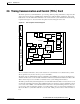
Timing Communication and Control (TCC+) Card
Install TCC+ cards in Slots 7 and 11 for redundancy. If the active TCC+ fails, traffic switches to the
protect TCC+. All TCC+ protection switches conform to protection switching standards of less than 50
ms.
The TCC+ features an RJ-45 10Base-T LAN port and an RS-232 DB9 type craft interface for user
interfaces. The TL1 craft port runs at 9600 bps.
Caution Cisco does not recommend operating the ONS 15454 with only one TCC+ card. To safeguard your
system, always operate in a redundant configuration.
4.6.1 TCC+ Card-Level Indicators
The TCC+ faceplate has eight LEDs. The first two LEDs are card-level indicators.
4.6.2 Network-Level Indicators
The TCC+ faceplate has eight LEDs. Six LEDs are network-level indicators.
.
Table 4-14 TCC+ Card-Level Indicators
Card-Level LEDs Definition
Red FAIL LED
Indicates a TCC+ hardware problem. Replace the unit if the FAIL LED
persists.
ACT/STBY LED
Green (Active)
Amber (Standby)
The ACT/STBY (Active/Standby) LED indicates that the TCC+ is active
(green) or in standby (amber). The ACT/STBY LED also provides the timing
reference and shelf control. When the TCC+ is writing to the Active or
Standby TCC+, its Active or Standby LED will blink.
To avoid memory corruption, only remove the TCC+ when it is in standby
and when the LED is not blinking.
Table 4-15 TCC+ System-Level Indicators
System-Level LEDs Definition
Red CRIT LED
Indicates a critical alarm in the network at the local node
Red MAJ LED
Indicates a major alarm in the network at the local node
Amber MIN LED
Indicates a minor alarm in the network at the local node
Red REM LED
Provides first-level alarm isolation. The REM LED turns red when an alarm
is present in one or several of the remote nodes.
Green SYNC LED
Indicates that node timing is synchronized to an external reference
Green ACO LED
After pressing the alarm cutoff (ACO) button, the green ACO LED
illuminates. The ACO button opens the audible closure on the backplane.
The ACO state is stopped if a new alarm occurs. After the originating alarm
is cleared, the ACO LED and audible alarm control are reset.