
Specifications


3-6
Cisco ONS 15454 Troubleshooting and Maintenance Guide
November 2001
Chapter 3 Maintenance
Fan-Tray Assembly Replacement
Note The 10-Gbps compatible shelf assembly (15454-SA-ANSI) and fan-tray assembly (15454-FTA3) are
required with the ONS 15454 XC-10G, OC-192, and OC-48 any slot (AS) cards.
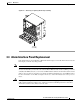
Procedure: Replace the Fan-Tray Assembly
To replace the fan-tray assembly, it is not necessary to move any of the cable management facilities. You
can remove the fan-tray assembly using the retractable handles and replace it by pushing until it plugs
into the receptacle on the back panel.
Caution Do not force a fan-tray assembly into place. Doing so can damage the connectors on the fan tray
and/or the connectors on the back panel of the shelf assembly.
Step 1 Remove the front door of the shelf assembly.
Step 2 Fold out the retractable handles at the outside edges of the fan tray.
Step 3 Slide the fan tray out of the shelf assembly by gently pulling on the handles. Figure 3-4 shows the
location of the fan tray.
Step 4 If you are replacing the fan-tray air filter and it is installed beneath the fan-tray assembly, slide the
existing air filter out of the shelf assembly and replace it before replacing the fan-tray assembly.
If you are replacing the fan-tray air filter and it is installed in the external bottom bracket, you can slide
the existing air filter out of the bracket and replace it at anytime.
Note The air filter will function with either side facing up but Cisco recommends that you install
the filter with the metal bracing facing up against the fan tray.
For more information on the fan-tray air filter, see the “Air Filter Inspection and Replacement” section
on page 3-1.
Step 5 Slide the fan tray into the shelf assembly until the electrical plug at the rear of the tray plugs into the
corresponding receptacle on the backplane.
Step 6 To verify that the tray has plugged into the backplane, check that the LCD on the front of the fan tray is
activated.