
Specifications


3-5
Cisco ONS 15454 Troubleshooting and Maintenance Guide
November 2001
Chapter 3 Maintenance
Fan-Tray Assembly Replacement
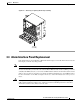
Figure 3-3 Inserting or removing a disposable fan-tray air filter
Step 8
Slide the fan-tray assembly into the shelf assembly until the electrical plug at the rear of the tray plugs
into the corresponding receptacle on the backplane.
Step 9 To verify that the tray is plugged into the backplane, ensure that the LCD on the front of the fan-tray
assembly is activated.
Step 10 Close the cable management tray.
Step 11 Raise the hinged panel at the front of the cable management tray.
Step 12 Close the front covers of the fiber management area.
Step 13 Replace the front door of the shelf assembly.
3.2 Fan-Tray Assembly Replacement
If one or more fans fail on the fan-tray assembly, replace the entire assembly. You cannot replace
individual fans. The red Fan Fail LED on the front of the fan tray illuminates when one or more fans fail.
The red Fan Fail LED clears after you install a working fan tray.
Caution The 15454-FTA3 fan-tray assembly can only be installed in ONS 15454 Release 3.1 shelf assemblies
(15454-SA-ANSI, P/N: 800-19857). It includes a pin that does not allow it to be installed in ONS
15454 shelf assemblies released before ONS 15454 Release 3.1 (15454-SA-NEBS3E,
15454-SA-NEBS3, and 15454-SA-R1, P/N: 800-07149). Equipment damage can result from
attempting to install the 15454-FTA3 in a non-compatible shelf assembly.
34511
Fan tray filter