
Specifications


2-24
Cisco ONS 15454 Troubleshooting and Maintenance Guide
November 2001
Chapter 2 General Troubleshooting
2.3.13 Calculate and Design IP Subnets
Cisco provides a free online tool to calculate and design IP subnets. Go to
http://www.cisco.com/techtools/ip_addr.html. For information about ONS 15454 IP capability, refer to
the Cisco ONS 15454 Installation and Operations Guide.
2.3.14 Ethernet Connections
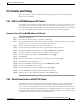
You can fix most connectivity problems in an Ethernet network by following a few guidelines. See
Figure 2-12 when consulting the steps in the following procedure.
Figure 2-12 Ethernet connectivity reference
Procedure: Verify Ethernet Connections
Step 1 Check for SONET alarms on the STS-N that carries the VLAN #1 Ethernet circuit. Clear any alarms by
looking them up in the “Alarm Troubleshooting” chapter.
Step 2 Check for Ethernet-specific alarms. Clear any present alarms by looking up that alarm in the “Alarm
Troubleshooting” chapter.
Step 3 Verify that the ACT LED on the Ethernet card is green.
Step 4 Verify that Ports 1 and 3 on ONS 15454 #1 and Ports 1 and 2 on ONS 15454 #2 have green link-integrity
LEDs.
Step 5 If no green link-integrity LED exists for any of these ports:
a. Verify physical connectivity between the ONS 15454s and the attached device.
b. Verify that the ports are enabled on the Ethernet cards.
c. Verify that you are using the proper Ethernet cable and that it is wired correctly, or replace the cable
with a reliable straight-through Ethernet cable.
d. Check the Status LED on the Ethernet card faceplate to ensure the card booted up properly. This
LED should be steady green. If necessary, remove and reinsert the card and allow it to reboot.
Virtual
LAN # 1
Device "A"
192.168.1.25
255.255.255.0
VLAN #1 Member
Device "C"
192.168.1.50
255.255.255.0
VLAN #1 Member
Device "D"
192.168.1.100
255.255.255.0
VLAN #1 Member
ONS 15454 #1
Port #1 VLAN #1
Port #3 VLAN #1
ONS 15454 #2
Port #1 VLAN #1
Port #2 VLAN #1
Device "B"
192.168.1.75
255.255.255.0
VLAN #1 Member
32167