
Specifications


2-11
Cisco ONS 15454 Troubleshooting and Maintenance Guide
November 2001
Chapter 2 General Troubleshooting
Step 7 Leave the Bidirectional check box checked and click Next.
Step 8 In the Circuit Source dialog box, fill in the same card and port where you performed the first loopback
test (the DS-N card in the source node).
Step 9 Click Next.
Step 10 In the Circuit Destination dialog box, use the source node OC-N card and port.
Step 11 Click Next and Finish.
Step 12 Confirm that the newly-created circuit appears with a direction column showing a 2-way circuit.
Step 13 Log into the destination node.
Step 14 For the second circuit, click the Circuits tab and click the Create button.
Step 15 Give the circuit an easily-identifiable name, such as hairpin2.
Step 16 Set Circuit Type and Size to your normal preferences.
Step 17 Uncheck the Bidirectional check box and click Next.
Step 18 In the Circuit Source dialog box, fill in the destination OC-N card and port.
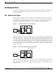
The OC-N card must be the other end of the fiber span originating from the OC-N card in Step 10. For
example in a typical east-to-west slot configuration, a slot 6 OC-N card on the source node is one end of
the fiber span, and the slot 12 OC-N card on the destination node is the other end. Figure 2-7 illustrates
the slot to fiber span relationship.
Step 19 Click Next.
Step 20 In the Circuit Destination dialog box, use the same card and port from the Circuit Source dialog box.
Step 21 Click Finish.
Step 22 Confirm that the second newly-created circuit appears with a direction column noting a 1-way circuit.
Step 23 Double-click the circuit to display the network view.
Step 24 Verify that the circuits connect to the correct slots. For example, source node/Slot 6 (east slot) to
destination node/Slot 12(west slot). If two east or two west slots are connected, the circuit will not work.
Except for the distinct slots, all other circuit information, such as ports, should be identical.
Step 25 If the test set is not already sending traffic, send test set traffic on the loopback circuit.
Step 26 Examine the test traffic received by the test set. Look for errors or any other signal information indicated
by the test set.
Step 27 If the test set indicates a good circuit, skip to the “Perform a Terminal Loopback on a Destination DS-N
Card” procedure on page 2-6.
Step 28 If the test traffic is not received or is poor quality, a problem may exist with the destination cross-connect
card, the source or destination OC-N card, or the fiber span. Test the destination cross-connect card, then
the OC-N cards, and then test the fiber span.
Caution Cross-connect manual switches (side switches) are service-affecting. Any live traffic on any
card in the node will endure a hit of up to 50 ms.
Step 29 Perform a software reset on the standby cross-connect card:
a. Determine the standby cross-connect card. On both the physical node and the CTC screen, the
ACT/STBY LED of the standby cross-connect card is amber, and the ACT/STBY LED of the active
cross-connect card is green.
b. Position the cursor over the standby cross-connect card.