
Technical data

TraverseEdge 2020 Applications and Engineering Guide, Chapter 3: System Applications
Release 5.0.x Turin Networks Page 3-29
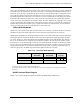
NUT is Non-Preemptable Unprotected Traffic. NUT requires the user to configure a given pair of timeslots
around the ring as NUT time slots. This pair corresponds to a working/protect BLSR time slot pair like 1
and 25 for an OC-48 ring or 10 and 106 for an OC-192 ring. Once the timeslot pair is configured as NUT
any connections made over those time slots operate as NUT connections. NUT connections are exactly
like UPSR unprotected connections. The connection is not protected and may be lost during some protec-
tion events. But, unlike PCA traffic, NUT traffic can not be overwritten by protect traffic during failure
events. That is why NUT timeslots are created in pairs - the lower numbered NUT time slot can no longer
use the corresponding upper number NUT time slot for protection and you are left with two unprotected
timeslots that will not be overwritten. NUT is applied on a timeslot by timeslot basis, so some timeslots
can be protected some can be PCA and others NUT on the same ring.
2-Fiber BLSR Bandwidth
BLSR nodes can terminate traffic that is fed from either side of the ring. Therefore, BLSRs are suited for
distributed node-to-node traffic applications such as interoffice networks and access networks.
BLSRs allow bandwidth to be reused around the ring and can carry more traffic than a network with traffic
flowing through one central hub. BLSRs can also carry more traffic than a UPSR operating at the same
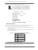
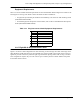
OC-n rate. Table 3-10 shows the bidirectional bandwidth capacities of two-fiber BLSRs. The capacity is
the OC-N rate divided by two, multiplied by the number of nodes in the ring minus the number of pass-
through STS-1 circuits. Pass through circuits eat away at the bandwidth available on a BLSR ring, there-
fore it is ideal to create shortest path cross connects between two nodes if possible. Likewise if a node is
equipped with 192 DS3s or equivalent bandwidth usage, there will be no capacity for pass-through con-
nections at the point in the BLSR rings and alternate paths will have to be created.
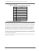
Table 3-10 Two-Fiber BLSR Capacity
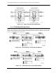
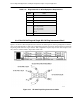
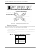
BLSR Functional Block Diagram
Figure 3-27 is a functional block diagram of operation for BLSR Ring configurations.
OC Rate Working
Bandwidth
Protection
Bandwidth
Ring
Capacity
OC-192 STS1-96 STS 97-192
96 x N
1
- PT
2
OC-48 STS 1-24 STS 25-48 24 x N - PT
1
N equals the number of nodes configured as BLSR nodes.
2
PT equals the number of STS-1 circuits passed through nodes in the ring (capacity can vary depending on the traf-
fic pattern).