
Technical data

TraverseEdge 2020 Applications and Engineering Guide, Chapter 3: System Applications
Release 5.0.x Turin Networks Page 3-27
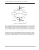
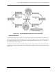
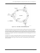
Figure 3-25 Three Node, 2-Fiber BLSR Operation
The SONET K1 and K2 bytes carry the information that governs BLSR protection switches. Each BLSR
node monitors the K bytes to determine when to switch the SONET signal to an alternate physical path.
The K bytes communicate failure conditions and actions taken between nodes in the ring. In a BLSR ring
the protected traffic in the lower numbered time slots is wrapped back into the upper numbered timeslots
when there is an equipment or fiber failure. The BLSR mechanism ensures the wrapping process occurs in
less than 50 ms.
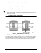
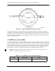
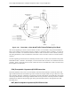
If a break occurs on one fiber, working traffic targeted for a node beyond the break switches to the protect
bandwidth on the second fiber. The traffic travels in reverse direction on the protect bandwidth until it
reaches its destination node. Figure 3-26 shows how traffic is rerouted following a line break between
Node 1 and Node 2.