
Technical data

TraverseEdge 2020 Applications and Engineering Guide, Chapter 3: System Applications
Release 5.0.x Turin Networks Page 3-25
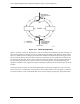
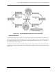
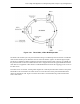
Figure 3-24 compares the basic functions and equipment requirements of the TE-2020 ADM when config-
ured as a UPSR node versus the Linear ADM node. Clearly the advantages of the UPSR can be seen here.
The linear ADM requires twice the high-speed equipment and fiber allotment of a UPSR node, which has
built in route diversity.
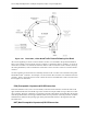
Figure 3-24 TE-2020 UPSR vs. ADM
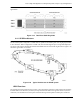
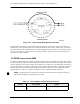
3.6 BLSR vs UPSR
The TE-2020 offers both Unidirectional Path Switch Ring (UPSR) and 2 Fiber Bi-directional Line Switch
Ring (2F-BLSR) configurations. UPSR rings offer ease of management and vendor interoperability while
BLSR is best suited for distributed node-to-node traffic applications such as a backbone ring. UPSR is
best suited for rings where traffic concentrates at a single node (access rings). BLSR rings allow band-
width to be reused around the ring and can carry more traffic than a UPSR ring operating at the same OC-
n rate in a multi-node environment. BLSR maximizes ring bandwidth with mesh topologies.
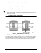
Transmission Charac-
teristics
Working and protect channels carry
data to far-end and bring data from
far-end. High speed facility switches
in the event of fiber failure.
Both channels transmit and receive to/from
both ring directions. Path terminating facil-
ity makes the signal selection. Full protec-
tion for entire signal path of each STS-1
tributary.
Channel units Four high-speed channel units, work-
ing and protect for each direction.
Two high-speed channel units, one for each
direction.
Traffic route All fibers follow same route (unless
diverse routing is used).
Typically two separate routes for each
STS-1.
Impact in event of
fiber cut.
Possible node isolation. Typically no node isolation.
Table 3-9 Linear ADM vs. 2-Fiber UPSR Architecture
Feature Linear ADM UPSR