
Technical data

TraverseEdge 2020 Applications and Engineering Guide, Chapter 3: System Applications
Page 3-24 Turin Networks Release 5.0.x
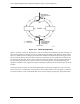
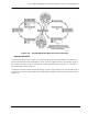
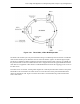
Figure 3-23 Unprotected UPSR Operation Example
In this example, two STS-3c-7v GbE interfaces are provisioned at Node A and Node D. The first GbE
PLM traffic is connected through Node E to Node D and the user has selected “Unprotected” connections.
The same is done for the GbE PLM 2 but it is directed through Node B and Node C to reach Node D, there-
fore only 21 circuits are provisioned on each direction of traffic. This allows twice as much traffic to be
carried on the UPSR as normal.
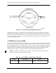
3.5 UPSR versus Linear ADM
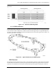
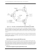
The 2-fiber UPSR configuration consists of identical signals running in opposite directions around the ring
to create route diverse paths. One direction functions as active, and one functions as standby. This configu-
ration is designed to prevent loss of traffic when a fiber is cut. If a fiber cut occurs that affects transmission,
the other direction acts as protection. When the received signal on the active fiber is degraded, the path-ter-
minating node at the far-end selects the standby path, thus, the architecture of the UPSR node protects
against traffic loss. Table 3-9 compares the features of linear ADMs and UPSR architecture.
NOTE: The signal path is the end-to-end connection between the node that originates the STS-1
signal and the node that terminates the STS-1 signal.
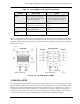
Table 3-9 Linear ADM vs. 2-Fiber UPSR Architecture
Feature Linear ADM UPSR
Fiber Count Four fibers for each direction of traf-
fic.
Two fibers running in opposite ring direc-
tions.