
Technical data

TraverseEdge 2020 Applications and Engineering Guide, Chapter 3: System Applications
Page 3-22 Turin Networks Release 5.0.x
1) Tributary signals are bridged and transmitted through both the east and
west optical PLMs at the STS path-originating node.
2) Along the route, the signals are passed through UPSR nodes located
between the origination and termination point of the STS path.
3) Both copies are received at the far-end STS path-terminating node.
4) The far-end node selects the better signal as the active channel.
NOTE: A single UPSR node can act as the path-terminating node for one or more STS-1/STS-1-
Xv/STS-3c/STS-3c-Xv/STS-12c/STS-48c/STS-192c signals while passing through the other com-
ponents of the optical path.
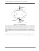
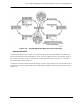
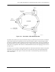
3.4.2 UPSR Functional Block Diagram
Figure 3-21 is a functional block diagram of operation for UPSR Ring configurations.
Figure 3-21 Traffic Flow through a UPSR Node
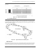
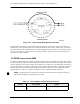
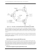
UPSR Ring Interconnect Topology
The TE-2020 can operate in a UPSR ring interconnect mode for OC-48/OC-192 rings. This configuration
uses a single node operating as an ADM on two separate ring networks. It can add/drop traffic for both
rings to local interfaces and can cross-connect traffic between the two rings. Refer to Figure 3-22.