
Technical data


TraverseEdge 2020 Applications and Engineering Guide, Chapter 7: Optical Link Design
Page 7-18 Turin Networks Release 5.0.x
Notes:
1
The OC-192 ITU LR module is listed int he link distance tables but the ULR version is not. This
is because the ULR version is intended for multi-span applications. To request link engineering
assistance for multi-span applications please inquire with your Turin Networks sales representa-
tive.
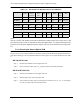
7.3.2 Choosing the Correct Optical PLM
The previous section provided a method of calculating a theoretical maximum transmission distance for
each offered PLM type. The recommended method of choosing the correct optical PLM for the TE-2020
is:
OC-3 & OC-12 Links
Step 1 Measure the attenuation on the target fiber link
Step 2 Select a PLM for which power, P
T
is greater than the measured attenuation
OC-48 & OC-192 Links
Step 1 Measure the attenuation on the target fiber link
Step 2 Measure dispersion on the target fiber link
Step 3 Select a PLM for which power (less margin and connector loss: P
T
– M – L
c
) and disper-
sion, D
T
, are greater than the measured values.
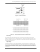
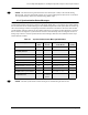
OC-48 LR-1 1200 1.5 800.0 -2 -28 0.45 51.11 51.1 (loss)
OC-48 IR-1 800 1.5 533.3 -5 -18 0.455 21.98 21.9 (loss)
OC-12 LR-1 92 1.5 61.3 -3 -28 0.45 48.89 48.8 (loss)
OC-12 IR-1 46 1.5 30.6 -15 -28 0.45 22.22 22.2 (loss)
OC-3 LR-1 246 1.5 164.0 -5 -34 0.45 57.78 57.7 (loss)
OC-3 IR-1 96 1.5 64.0 -15 -28 0.45 22.22 22.2 (loss)
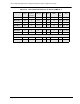
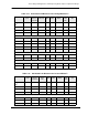
Table 7-18 Calculated Link Distances for Lucent AllWave™
Module Name Dispersion
(ps/nm)
Dispersion
Parameter
(ps/nm-km)
Dispersion
Limit
(km)
Ptmin
(dBm)
Prmin
(dBm)
Attenuation
(dB/km)
Loss
Limit
(km)
Total Reach
(km)