
Technical data

TraverseEdge 2020 Applications and Engineering Guide, Chapter 7: Optical Link Design
Release 5.0.x Turin Networks Page 7-13
Power Penalty (P
o
)
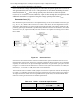
Optical path power penalty (measured in dB), P
o
, accounts for the total degradation along the opti-
cal path between points S and R from reflections, jitter, intersymbol interference, mode-partition
noise and laser chirp as shown in Figure 7-1. Optical path power penalty is not used directly in the
optical link budget process described in Chapter 7 Calculating Single-Span Fiber Link Budgets.
Rather, the System Margin, described below is used to ensure this power penalty and any addi-
tional operating margin desired is accounted for.
Fiber & Splice Loss (L
f
)
Loss or attenuation of an optical signal through fiber is attributable to a number of phenomena,
such as Rayleigh scattering and waveguide attenuation, that absorb passing optical energy or
change its direction (i.e., scatter it out through the fiber cladding). The amount of loss incurred is a
primarily a function of the transmit wavelength (range) and the fiber type. The two optical wave-
length transmission windows typically used for SONET signals are 1310nm and 1550nm. Typical
attenuation values for Conventional Single Mode Fiber (C-SMF; e.g. Corning’s© SMF28®) are
provided in Table 7-15 . It should be noted that attenuation in older C-SMF may be a bit higher
while it may be somewhat lower in new.
Fiber splices, used at installation when connecting spans (from different reels) or when repairing
damaged fibers, are also a source of attenuation. Splice attenuation can vary widely in the field,
depending on the age of the splice (splicing equipment has improved over the years) and the qual-
ity of workmanship, but are typically 0.1dB to 0.2dB each. The number of splices along actual
routes also varies widely depending on construction activity and service churn.
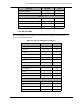
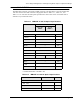
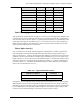
MPO – Multi Mode Flat Polish 0.75 N/A
SC – Single Mode Ultra PC 0.3 55
SC – Multi Mode Standard PC 0.5 25
LC – Single Mode Ultra PC 0.3 55
LC –Multi Mode Standard PC 0.5 25
ST – Single Mode Ultra PC 0.3 55
ST – Multi Mode Standard PC 0.5 25
FC – Single Mode Ultra PC 0.3 55
FC – Multi Mode Standard PC 0.5 25
MT-RJ – Multi Mode Flat Polish 0.75 N/A
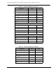
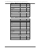
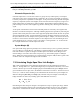
Table 7-15 Typical Attenuation Values
Transmission Window Attenuation
1310nm 0.5dB/km
1550nm 0.275dB/km