
Technical data

TraverseEdge 2020 Applications and Engineering Guide, Chapter 7: Optical Link Design
Release 5.0.x Turin Networks Page 7-11
7.2 Optical Link Design
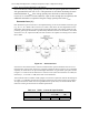
Determining the reach, or reliable transmission distance, achievable using a given combination of
optical transmitter, physical fiber span (including splices and connectors) and receiver is com-
monly accomplished using the process of “Optical Link Budgeting.” This section describes the
various factors relating to fiber optic transmission link budgets. These factors are then applied to
the calculation of the approximate reach that may be achieved with the various optical interface
options available for the TE-2020 system.
For single-span applications, the primary parameters used in determining span length are:
• Optical output power level
• Receiver Sensitivity
• Connector Loss
• Power Penalty
• Fiber & Splice Loss
• Chromatic dispersion
• Safety margin
Each of these factors is defined in the following sections, followed by a section providing general
link design formulae and examples.
NOTE: While the design of each span of a multiple-span application (optically amplified
and dispersion compensated) may be calculated in similar fashion to a single span, the ulti-
mate reach across multiple spans is typically limited by the accumulation of optical noise.
Design of multiple-span applications is outside the scope of this document. For assistance
with such designs please contact your Turin Networks sales representative.
7.2.1 Optical Link Design Parameters
Optical Output Power Level (P
tmin
)
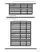
Optical output power (expressed in dBm) is the power launched into the fiber ‘pigtail’
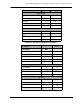
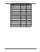
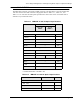
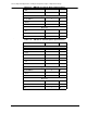
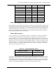
attached to the laser diode transmitter. In Table 7-1 through Table 7-13 , minimum and
maximum optical output power levels (P
tmin
and P
tmax
, respectively) are provided for each
TE-2020 Optical Physical Layer Module (PLM) type. The P
tmin
value is the output power
guaranteed available at end of service life (20 years) across the full operating temperature
range (-5C to +55C ambient or 0C to 40C with tunable PLMs). To ensure reliable trans-
mission through the life of deployment, the P
tmin
parameter is used in all optical link bud-
get calculations.
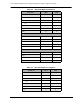
Optical Receiver Sensitivity (P
rmin
, P
rmax
)
The optical receiver sensitivity is the average optical power level at which the optical sig-
nal can be recovered with guaranteed bit error rate of 10
-12
. Like the optical output power
parameter, receiver sensitivity is given as both minimum and maximum (P
rmin
and P
rmax
,
respectively) in Table 7-1 through Table 7-13 . However, both parameters, P
rmin
and