
Technical data


TraverseEdge 2020 Applications and Engineering Guide
Release 5.0.x Turin Networks Page xiii
Table of Figures
Item Page
Chapter 1 TE-2020 System Introduction
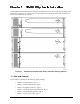
Figure 1-1 TE-2020 System with OTS2, ETS1, and ETS2 Tributary Shelves.................................................... 1-1
Chapter 2 System Features
Figure 2-1 TE-2020 Main Shelf Components ..................................................................................................... 2-2
Figure 2-2 OTS2 Shelf Components .................................................................................................................. 2-2
Figure 2-3 ETS1 Shelf Components................................................................................................................... 2-3
Figure 2-4 ETS2 Shelf Components................................................................................................................... 2-4
Figure 2-5 TN-Sight GUI Display........................................................................................................................ 2-7
Figure 2-6 TN-Xpert GUI Display........................................................................................................................ 2-8
Figure 2-7 Test Architecture ............................................................................................................................... 2-9
Figure 2-8 Nine Primary Test Access Modes ................................................................................................... 2-10
Chapter 3 System Applications
Figure 3-1 TE-2020 Main Shelf Identifiers.......................................................................................................... 3-2
Figure 3-2 OTS2 Shelf Identifiers ....................................................................................................................... 3-2
Figure 3-3 ETS1 Shelf Identifiers........................................................................................................................ 3-2
Figure 3-4 ETS2 Shelf Identifiers........................................................................................................................ 3-3
Figure 3-5 TE-2020 OC-192 Node with Eight GbE Drops.................................................................................. 3-3
Figure 3-6 TE-2020 OC-48 Node with Four GbE Drops..................................................................................... 3-4
Figure 3-7 Unprotected Hub Application............................................................................................................. 3-6
Figure 3-8 Terminal Configuration ...................................................................................................................... 3-7
Figure 3-9 Linear ADM Terminal Configuration.................................................................................................. 3-7
Figure 3-10 1+1 Terminal (ADM) System Flow .................................................................................................... 3-8
Figure 3-11 TE-2020 Main Shelf Terminal............................................................................................................ 3-9
Figure 3-12 TE-2020 Terminal with 192 DS3/EC-1 Drops ................................................................................. 3-11
Figure 3-13 OC-192 1+1 Terminal Configuration with 16 Protected OC-12 Drops ............................................ 3-12
Figure 3-14 TE-2020 Terminal with Optical and DS3/EC-1 Tributaries.............................................................. 3-14
Figure 3-15 Dual OC-48 Terminal/Linear with Mixed Tributaries .......................................................................3-16
Figure 3-16 Regenerator Application Example................................................................................................... 3-18
Figure 3-17 TE-2020 as a Regenerator ............................................................................................................. 3-19
Figure 3-18 UPSR Ring Operation ..................................................................................................................... 3-20
Figure 3-19 Two-Fiber UPSR Ring Node ........................................................................................................... 3-21
Figure 3-20 Typical Architecture for UPSR System............................................................................................ 3-21
Figure 3-21 Traffic Flow through a UPSR Node ................................................................................................. 3-22
Figure 3-22 TE-2020 OC-48 Dual Ring Interconnect Operation......................................................................... 3-23
Figure 3-23 Unprotected UPSR Operation Example.......................................................................................... 3-24
Figure 3-24 TE-2020 UPSR vs. ADM................................................................................................................. 3-25
Figure 3-25 Three Node, 2-Fiber BLSR Operation............................................................................................. 3-27
Figure 3-26 Three Node, 2-Fiber BLSR Traffic Pattern Following Line Break.................................................... 3-28
Figure 3-27 Traffic Flow through a BLSR Node.................................................................................................. 3-30
Figure 3-28 Fiber Routing in an OC-192 Ring Network......................................................................................3-30
Figure 3-29 Fiber Routing in an OC-48 Ring Network........................................................................................ 3-30
Figure 3-30 TE-2020 OC-192 Ring Node........................................................................................................... 3-32
Figure 3-31 TE-2020 Ring Node with 192 DS3/EC-1 Drops .............................................................................. 3-33
Figure 3-32 Ring Application with an OTS2........................................................................................................ 3-35
Figure 3-33 TE-2020 Triple Ring Interconnect Node.......................................................................................... 3-36
Figure 3-34 TE-2020 Eight Ring Interconnect Node........................................................................................... 3-38
Figure 3-35 TE-2020 Dual UPSR Node with Mixed Tributary Drops.................................................................. 3-39