
Technical data

TraverseEdge 2020 Applications and Engineering Guide, Chapter 4: Equipment Protection
Release 5.0.x Turin Networks Page 4-5
provide little advantage.
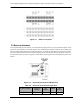
When electrical modules are protected and the working unit fails, traffic is rerouted to the protection unit.
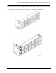
The red FAIL indicator on the failed unit front panel is turned on. A fully equipped DS3/EC1 Tributary
Shelf provides a redundant protection DS3/EC-1 PLM in the top left PLM slot. Refer to Figure 4-6. If the
CCT detects an equipment failure in one of the working units, it automatically switches to the protection
unit to accomplish that function.
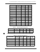
Figure 4-6 DS3/EC1 Tributary Shelf Equipment Protection Scheme
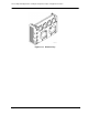
When utilizing 1:4 protection in the DS3/EC1 Tributary Shelf, the slots between the working and protect
PLMs must be populated. Leaving an empty slot between the working and protect card breaks the protec-
tion bus on the backplane. The resulting configuration would provide a 1:N protection for any PLMs in
adjacent slots to the protect card, and unprotected for any PLMs not in adjacent slots. Refer to Figure 4-7.
NOTE: When an auto switch has occurred due to a PLM hard failure, it will switch to protect. If a
failure condition previously existed on another PLM that is residing on the protect module, the sec-
ondary failure will go into a LOS condition.
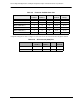
Figure 4-7 Unprotected DS3/EC-1 Configuration (example)
A “PLM Unprotected” alarm will be declared on all PLMs that are or become unprotected as a result of a
card being deleted or removed in a 1:N protection group. If the user inserts a PLM in slot 3 of Figure 4-7,
the protection group will automatically expand to protect the PLMs in slots 4 and 5 creating a 1:4 protec-
tion group. A “PLM Protected” alarm will be declared on all PLMs that become protected as a result of
PLM insertion into the shelf, and subsequently, the PLM Unprotected alarm will be cleared.
The ETS2 shelf has provisions for only two DS3/EC1 PLMs and supports a 1:1 protection mechanism.