
Technical data


TraverseEdge 2020 Applications and Engineering Guide, Chapter 4: Equipment Protection
Release 5.0.x Turin Networks Page 4-3
The CCTs require redundant -48Vdc nominal power inputs within a tolerance of -42.5Vdc to -56.5Vdc, to
be capable of normal operation in the event that one of the power inputs fails.
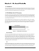
4.4 DS3/EC-1 CCT Protection
The DS3/EC-1 CCTs provide the interface for all administrative commands from the TE-2020 Main Shelf
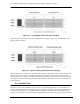
and traffic from the electrical interfaces to the TE-2020 Main Shelf. They reside only in the DS3/EC1 Trib-
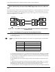
utary Shelf in a side by side redundant configuration as shown in Figure 4-3.
Figure 4-3 ETS1 and ETS2 CCT Card Placement
The ETS1 or ETS2 CCTs supply the following functionality:
• Redundant LEI interface for the shelf
• Redundant synchronization interface from the TE-2020 Main Shelf
• Redundant management interface from the TE-2020 Main Shelf
• Redundant shelf management and control
4.5 PLM Protection
PLMs are the Physical Layer Modules that actually interface with the external equipment. The PLMs con-
sist of optical PLMs (OC-3, OC-12, OC-48, OC-192, and GbE), and electrical PLMs (DS1, FastE, DS3/
EC-1).
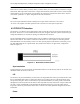
4.5.1 Optical PLM
The optical PLMs can be configured for protected or unprotected applications. In a protected application,
the upper (row 1) and lower (row 2) PLM on the left or the right operate in a working and protect group
(denoted as Group 1 and Group 2). The Row 3 PLM slots are in a separate working and protect group.
Refer to Figure 4-5 below.