Turin Networks Inc. TraverseEdge 2020 System Documentation Applications and Engineering Guide Software Release 5.0.x Publication Date: April 2007 Document Number: 800-0015-50 Rev.
Copyright © 2007 Turin Networks, Inc. All rights reserved. This document contains proprietary and confidential information of Turin Networks, Inc., and may not be used, reproduced, or distributed except as authorized by Turin Networks. No part of this publication may be reproduced in any form or by any means or used to make any derivative work (such as translation, transformation or adaptation) without written permission from Turin Networks, Inc.
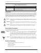
TraverseEdge 2020 Applications and Engineering Guide PREFACE Revision History The following lists the sections of this document affected by any informational changes: Section Issue All Date 01 Reason For Change 4/2007 First Release 5.0 Version (Preliminary) Related Documents The following documents pertain to Turin’s TraverseEdge 2020 (TE-2020) optical transport equipment. For online documentation, visit Turin’s website and register for access to the web portal at www.turinnetworks.
TraverseEdge 2020 Applications and Engineering Guide Table 2 TN-Xpert™ Document List Document Title TN-Xpert Users Guide Description Provides information vital for proper operation and maintenance of Turin Networks TE2020 and TE-206 systems. Information provided deals with processes and procedures for turn-up, test, maintenance duties, input command sequences, valid parameters, and expected responses using TN-Xpert™.
TraverseEdge 2020 Applications and Engineering Guide FCC Warning The TPE-1200 system has been tested and found to comply with the limits for a Class A digital device, pursuant to Part 15 of the FCC Rules. These limits are designed to provide reasonable protection against harmful interference when this equipment is operated in a commercial environment.
TraverseEdge 2020 Applications and Engineering Guide If You Need Assistance If you need assistance while working with the TE-1200 product, contact the Turin Technical Assistance Center (TAC). See the “Query and Contact Information Matrix” table above. TAC is available 8:00AM to 6:00PM Central Time, Monday through Friday (business hours). When the TAC is closed, emergency service only is available on a callback basis. E-mail support (24-hour response) is also available through: support-vlx@turinnetworks.
TraverseEdge 2020 Applications and Engineering Guide FTP GbE GFP GMPLS GNE GUI HTTP IR LAN LDCC LDF LEI LR LSP LTE MAC MMF NEBS NE NTP File Transfer Protocol Giga-bit Ethernet Generic Framing Procedure Generalized Multi-Protocol Label Switching Gateway Network Element Graphical User Interface Hyper-text Transfer Protocol Intermediate Reach Local Area Network Line Data Communications Channel Lightwave Distribution Frame Local Equipment Interconnect Long Reach Label Switched Path Line Terminating Equipment
TraverseEdge 2020 Applications and Engineering Guide TBD TCP/IP TID TL-1 TX UL UPSR VC Vdc VLAN VPN VR WDM Page viii To Be Determined Transport Control Protocol/Internet Protocol Target Identifier Transaction Language Level 1 Transmit Underwriters Laboratories Unidirectional Path Switched Ring Virtual Concatenation Voltage - Direct Current Virtual Lan Virtual Private Network Very Long Reach Wave Division Multiplexing Turin Networks Release 5.0.
TraverseEdge 2020 Applications and Engineering Guide Table of Contents Item Page PREFACE Revision History .................................................................................................................................................... iii Related Documents ............................................................................................................................................... iii Precautions ........................................................................
TraverseEdge 2020 Applications and Engineering Guide 3.8.6 Dual OC-48 Ring Node with Mixed Drops......................................................................................... 3-39 3.8.7 OC-192 with mixed GbE and DS3 Drops .......................................................................................... 3-41 3.8.8 TE-2020 OC-192 Ring Ethernet Aggregation and Transport ............................................................ 3-43 3.9 DS3 Transmux and VT Grooming ......................
TraverseEdge 2020 Applications and Engineering Guide 6.5 Bandwidth Allocation .................................................................................................................................... 6-1 6.5.1 TE-2020 Main Shelf ............................................................................................................................ 6-2 6.5.2 OTS2 Shelf..............................................................................................................................
TraverseEdge 2020 Applications and Engineering Guide Page xii Turin Networks Release 5.0.
TraverseEdge 2020 Applications and Engineering Guide Table of Figures Item Page Chapter 1 TE-2020 System Introduction Figure 1-1 TE-2020 System with OTS2, ETS1, and ETS2 Tributary Shelves.................................................... 1-1 Chapter 2 System Features Figure 2-1 TE-2020 Main Shelf Components ..................................................................................................... 2-2 Figure 2-2 OTS2 Shelf Components ...........................................................
TraverseEdge 2020 Applications and Engineering Guide Figure 3-36 TE-2020 OC-192 Node with Four GbE and 96 DS3 Drops............................................................. 3-41 Figure 3-37 TE-2020 OC-192 Node with GbE, DS1 and DS3 Drops ................................................................. 3-43 Figure 3-38 DS3 TMUX M13 Multiplexing Flow Diagram ................................................................................... 3-45 Figure 3-39 DS3 TMUX VT Grooming Flow Diagram.............
TraverseEdge 2020 Applications and Engineering Guide Figure 6-2 LEI Cabling Example - TE-2020 Main Shelf with One OTS2 with Two LEIs..................................... 6-3 Figure 6-3 LEI Cabling Example - TE-2020 Main Shelf with One OTS2 with Three LEIs .................................. 6-4 Figure 6-4 LEI Cabling Example - TE-2020 Main Shelf with One OTS2 with four LEIs ..................................... 6-4 Figure 6-5 LEI Cabling Example - TE-2020 Main Shelf with One ETS1............................
TraverseEdge 2020 Applications and Engineering Guide Page xvi Turin Networks Release 5.0.
TraverseEdge 2020 Applications and Engineering Guide List of Tables Item Page PREFACE TE-2020™ Document List.......................................................................................................................................... iii TN-Xpert™ Document List .........................................................................................................................................
TraverseEdge 2020 Applications and Engineering Guide Table 7-2 OC-12 Laser Specifications.................................................................................................... 7-2 Table 7-3 OC-48 IR Optical Parameters................................................................................................. 7-3 Table 7-4 OC-48 LR Optical Parameters................................................................................................
Chapter 1 TE-2020 System Introduction This document describes the engineering design and applications of the Turin Networks TE-2020 product family shown in Figure 1-1 It can be used as an aid to planners in optimizing design and controlling cost for their individual network solutions. Figure 1-1 TE-2020 System with OTS2, ETS1, and ETS2 Tributary Shelves 1.
TraverseEdge 2020 Applications and Engineering Guide, Chapter 1: TE-2020 System Introduction • • • • Page 1-2 Chapter 8 “Node Synchronization‚ page 1” Chapter 9 “Operations Communications‚ page 1” Chapter 10 “Network Management‚ page 1” Chapter 11 “Interoperability‚ page 1” Turin Networks Release 5.0.
Chapter 2 System Features The following features are detailed in this chapter: 2.1 Overview 2.2 Hardware Features 2.3 Software Features 2.3.1 Element Level Web Based Graphical User Interface 2.3.2 Network Level Graphical User Interface 2.3.3 SNMP Traps 2.4 TE-206 2.5 DTAU Feature 2.5.1 TSC/RTU - DTAU Feature Requirements 2.1 Overview The TE-2020 is a SONET OC-192 platform.
TraverseEdge 2020 Applications and Engineering Guide, Chapter 2: System Features Figure 2-1 TE-2020 Main Shelf Components The TE-2020 also features optional tributary shelves for additional bandwidth and interface capabilities. An OTS2 shelf provides additional optical interfaces, an ETS1 provides 48 DS3 interfaces, and an ETS2 provides for DS3, DS1, and FastE interface capabilities. Up to 4 tributary shelves can be equipped on one TE-2020 Main Shelf. Figure 2-2 shows an OTS2 and shelf components.
TraverseEdge 2020 Applications and Engineering Guide, Chapter 2: System Features ETS Fan Tray DS3 CCTs 4 WORKING 1 PROTECT DS3/EC1 PLMS Figure 2-3 ETS1 Shelf Components Figure 2-4 shows an ETS2 shelf equipped with two DS1 PLMs, 2 FastE PLMs, and 2 DS3/EC1 PLMs. Release 5.0.
TraverseEdge 2020 Applications and Engineering Guide, Chapter 2: System Features Various combinations of PLMs and tributary shelves can be obtained according to network requirements. ETS FAN TRAY SHOWN WITH 2 DS1 PLMS (TOP) AND 2 FASTE PLMS (BOTTOM) TWO DS3/EC1 PLMS IN A 1:1 PROTECTION GROUP Figure 2-4 ETS2 Shelf Components Other hardware features of the TE-2020 system are defined as: Physical Features • • • • • Building block architecture 19-inch or 23-inch rack mountable 2 RU (rack unit) 3.
TraverseEdge 2020 Applications and Engineering Guide, Chapter 2: System Features • • • • • • • • • • • • • • • • • • • • • • • • • • Front Ethernet Port Rear DB-9 RS-232 User Port Dual rear Ethernet connections Dual external synchronization BITS source inputs Dual derived DS1 external synchronization clock outputs DTAU Feature (added in Release 5.0 see 2.
TraverseEdge 2020 Applications and Engineering Guide, Chapter 2: System Features 2.3 Software Features Operational software features of the TE-2020 system are listed below: • • • • • • • • • • • • • • • • • • • • • • • • • • • • • • • • • • • • Page 2-6 Full performance monitoring Any timeslot to any timeslot 1920 x 1920 STS-1 cross connect matrix Optional 2.5Gbps or 5Gbps VT1.
TraverseEdge 2020 Applications and Engineering Guide, Chapter 2: System Features 2.3.1 Element Level Web Based Graphical User Interface TN-Sight is a craft element management tool that resides in Turin Networks’ TE-20xx products. It provides a simple and easy-to-use graphical user interface (GUI) enabling users to configure and maintain individual network elements within their networks without additional software installation.
TraverseEdge 2020 Applications and Engineering Guide, Chapter 2: System Features system and the topology view. For more details on the TN-Xpert EMS system, refer to the TN-Xpert Users Guide. Figure 2-6 TN-Xpert GUI Display 2.3.3 SNMP Traps The TE-2020 supports the generation of SNMP traps for alarm and event reporting. The user can configure up to three destination trap servers and the associated community string to receive the generated SNMP traps.
TraverseEdge 2020 Applications and Engineering Guide, Chapter 2: System Features 2.4 TE-206 To further enhance the TE-2020 traffic terminating capabilities, Turin Networks offers the TE-206 system. The TE-206 is an access oriented multi-service platform designed to extend the network application reach for the TE-2020 product family. The TE-206, although designed based on the TE-2020, may also be configured to work with other SONET hub nodes.
TraverseEdge 2020 Applications and Engineering Guide, Chapter 2: System Features b. Split (terminate) one or both directions of a circuit The TSC/RTU with which the test access feature must be interoperable is the Acterna® CENTEST™ test system. It would also be desirable to be compatible with the Spirent™ (acquired Hekimian) REACT/ BRTU product (however, Spirent is known to charge a considerable sum for compatibility). Test access may be on an in-service or out-of-service basis.
TraverseEdge 2020 Applications and Engineering Guide, Chapter 2: System Features 2.5.1 TSC/RTU - DTAU Feature Requirements Designation of Test Access Ports The TE-2020 supports provisioning of DS1 and DS3 port pairs as TAPs. Tellabs’ implementation of this capability is to add parameters to the ENT-T1 and ENT-T3 commands to designate specific T1 and T3 AIDs as TAPs. R.R4.1NE.TAP.
TraverseEdge 2020 Applications and Engineering Guide, Chapter 2: System Features RTRV-TAP-T3 Retrieves the status of a T3 TAP DISC-TACC Disconnects the identified TAP R.R4.1NE.TAP.7 Acterna CENTEST (and preferably Spirent BRTU) TSC/RTU compliant TL-1 commands connect, change access mode, and disconnect any DS1 circuit transported through a TE-2020 to/from a specified T1 TAP R.R4.1NE.TAP.
Chapter 3 System Applications This chapter describes different network applications related to deployment of the TE-2020 system. Refer to the following sections: 3.1 Unprotected 3.2 1+1 Terminal 3.3 TE-2020 Regenerator or Transponder 3.4 UPSR (Unidirectional Path-Switched Rings) 3.5 UPSR versus Linear ADM 3.6 BLSR vs UPSR 3.7 BLSR (Bi-directional Line Switched Rings) 3.8 General Ring Configuration Examples and Requirements 3.9 DS3 Transmux and VT Grooming 3.10 Gigabit Ethernet Applications 3.
TraverseEdge 2020 Applications and Engineering Guide, Chapter 3: System Applications Figure 3-1 Page 3-2 TE-2020 Main Shelf Identifiers Figure 3-2 OTS2 Shelf Identifiers Figure 3-3 ETS1 Shelf Identifiers Turin Networks Release 5.0.
TraverseEdge 2020 Applications and Engineering Guide, Chapter 3: System Applications Figure 3-4 ETS2 Shelf Identifiers 3.1 Unprotected 3.1.1 OC-192 with Gigabit Ethernet Figure 3-5 shows a typical configuration that maps line-rate Ethernet traffic from eight GbE ports into a single OC-192. Although not illustrated here, protected SONET operation (either 1+1, BLSR, or UPSR) is also possible. This configuration requires only two rack units of space.
TraverseEdge 2020 Applications and Engineering Guide, Chapter 3: System Applications Table 3-1 OC-192 Node with Eight GbE Drops Equipment Requirements QTY Part 1 TE-2020 Main Shelf 2 TE-2020 Main CCT 1 TE-2020 Main Fan Tray 1 OC-192 x1 PLM 4 GbE x2 PLM 1 OC-192 PLM Blank 3.1.2 OC-48 with Gigabit Ethernet Figure 3-6 is a typical configuration that maps line-rate Ethernet traffic from four GbE ports into two unprotected OC-48 ports. This configuration requires only two rack units of space.
TraverseEdge 2020 Applications and Engineering Guide, Chapter 3: System Applications • For detailed physical descriptions of the modules, refer to the TE-2020 Hardware Description Guide (800-0015-50). Table 3-2 OC-48 Node with Four GbE Drops Equipment Requirements QTY Part 1 TE-2020 Main Shelf 2 TE-2020 Main CCT 1 TE-2020 Main Fan Tray 2 OC-48 x1 PLM 2 GbE x2 PLM 1 OC-192 PLM Blank 3.1.
TraverseEdge 2020 Applications and Engineering Guide, Chapter 3: System Applications tributary shelves. Figure 3-7 Unprotected Hub Application 3.1.4 Unprotected UPSR The unprotected UPSR configurations of the TE-2020 system are discussed in section 3.4 “UPSR (Unidirectional Path-Switched Rings)” on page 19. 3.2 1+1 Terminal The TE-2020 Main Shelf can be used at each end of a 1+1 terminal span terminating a single unprotected, or two 1+1 protected, optical interfaces (OC-3, OC-12, OC-48, or OC-192).
TraverseEdge 2020 Applications and Engineering Guide, Chapter 3: System Applications Figure 3-8 Terminal Configuration The TE-2020 system supports linear ADM network configurations, at the OC-3, OC-12 and OC-48 line rates. Deploying linear ADMs between the two terminals discussed above creates an add/drop chain. A Linear ADM is a dual 1+1 Terminal that receives signals from one direction and passes them through to the next set of optics to continue traversing the network.
TraverseEdge 2020 Applications and Engineering Guide, Chapter 3: System Applications Figure 3-10 1+1 Terminal (ADM) System Flow Options with Terminal Applications The TE-2020 can be utilized with OTS2, ETS1, ETS2, or a combination of the three tributary shelves. The ETS1 can provide up to 48 DS3/EC-1 signals from four working 12-port DS3/EC-1 PLMs. The ETS2 can provide up to 168 DS1s, 24 FastE, or a combination of both signals.
TraverseEdge 2020 Applications and Engineering Guide, Chapter 3: System Applications Various combinations of the following interfaces are possible: • Up to 192 DS3s transported in STS-1 channels • Up to 192 EC-1s transported in STS-1 channels • Up to 40 protected or 80 unprotected OC-3 interfaces transported in STS-1 and/or STS-3c channels • Up to 40 protected or 80 unprotected OC-12 interfaces transported in STS-1, STS-3c, and/or STS-12c channels • Up to 24 protected or 48 unprotected OC-48 interfaces tra
TraverseEdge 2020 Applications and Engineering Guide, Chapter 3: System Applications • For physical layer module part numbers and availability, refer to the TE-2020 Ordering Guide (WR-D2020-ORD-050000). • For detailed physical descriptions of the modules, refer to the TE-2020 Hardware Description Guide (WR-D2020-HWD-050000). Table 3-3 Single Terminal Shelf Equipment Requirements QTY Part 1 TE-2020 Main Shelf 2 TE-2020 Main CCT 1 TE-2020 Main Fan Tray 2 OC-192 x1 PLM 4 OC-48 x1 PLM 3.2.
TraverseEdge 2020 Applications and Engineering Guide, Chapter 3: System Applications Figure 3-12 TE-2020 Terminal with 192 DS3/EC-1 Drops Equipment Requirements Table 3-4 shows module and shelf requirements for the TE-2020 Main Shelf configured as a terminal with ETS1 shelves providing 192 DS3/EC-1 drops. Refer to the following documents for more information: Release 5.0.
TraverseEdge 2020 Applications and Engineering Guide, Chapter 3: System Applications • For physical layer module part numbers and availability, refer to the TE-2020 Ordering Guide (WR-D2020-ORD-050000). • For detailed physical descriptions of the modules, refer to the TE-2020 Hardware Description Guide (WR-D2020-HWD-050000).
TraverseEdge 2020 Applications and Engineering Guide, Chapter 3: System Applications Equipment Requirements Table 3-5 shows module and shelf requirements for the TE-2020 Main Shelf configured as a 1+1 terminal node with 16 protected OC-12 drops. Refer to the following documents for more information: • For physical layer module part numbers and availability, refer to the TE-2020 Ordering Guide (WR-D2020-ORD-050000).
TraverseEdge 2020 Applications and Engineering Guide, Chapter 3: System Applications Figure 3-14 TE-2020 Terminal with Optical and DS3/EC-1 Tributaries The tributary shelves require LEI (Local Equipment Interconnect) connections to the TE-2020 Main Shelf in a protected pair arrangement. The total bandwidth capacity per protected LEI is one STS-48. With a maximum of four protected LEIs connected to an OTS2, the maximum trib shelf capacity is 192 STS-1s of bandwidth.
TraverseEdge 2020 Applications and Engineering Guide, Chapter 3: System Applications Table 3-6 1+1 OC-192 Terminal Shelf with Mixed Tributaries Equipment Requirements QTY Part 1 TE-2020 Main Fan Tray 2 OC-192 x1 PLM 4 OC-48 x1 PLM 1 OTS2 2 OTS2 CCT 1 OTS2 Fan Tray 3 Local Equipment Interconnect Cable Pair 4 OC-12 x4 PLM 1 ETS1 2 ETS1 CCT 1 ETS Fan Tray 5 DS3/EC1 PLM (twelve port) 3.2.
TraverseEdge 2020 Applications and Engineering Guide, Chapter 3: System Applications Figure 3-15 Dual OC-48 Terminal/Linear with Mixed Tributaries The Tributary Shelves require LEI (Local Equipment Interconnect) connections to the TE-2020 Main Shelf in a protected pair arrangement. The total bandwidth capacity per protected LEI is one STS-48. With a maximum of four protected LEI connected to an OTS2, the maximum trib shelf capacity is 192 STS-1s of bandwidth.
TraverseEdge 2020 Applications and Engineering Guide, Chapter 3: System Applications Table 3-7 Dual OC-48 Terminal/Linear with Mixed Tributaries Equipment Requirements QTY Part 1 TE-2020 Main Shelf 2 TE-2020 Main CCT 1 TE-2020 Main Fan Tray 4 OC-48 x1 PLM 1 OTS2 2 OTS2 CCT 1 OTS2 an Tray F Up to 4 OC-3 x4 PLM OC-12 x4 PLM OC-48 x1 PLM GbE x2 1 ETS1 2 ETS1 CCT 1 ETS Fan Tray 2 or 3 Local Equipment Interconnect Cable Pair 5 DS3/EC1 PLM (twelve port) 2 OC-192 PLM Blanks 3.
TraverseEdge 2020 Applications and Engineering Guide, Chapter 3: System Applications Figure 3-16 Regenerator Application Example Equipment Requirements Table 3-8 shows module and shelf requirements for the TE-2020 Main Shelf configured to handle regenerator applications. Refer to the following documents for more information: • For physical layer module part numbers and availability, refer to the TE-2020 Ordering Guide (WR-D2020-ORD-050000).
TraverseEdge 2020 Applications and Engineering Guide, Chapter 3: System Applications Figure 3-17 Table 3-8 TE-2020 as a Regenerator Regenerator Application Equipment Requirements QTY Part 1 TE-2020 Main Shelf 2 TE-2020 Main CCT 1 TE-2020 Main Fan Tray 2 OC-192 x1 PLM 4 Optical PLM Blanks 3.4 UPSR (Unidirectional Path-Switched Rings) The unidirectional path-switched ring (UPSR) provides protection from fiber cuts for each VT1.5 or STS on an individual basis.
TraverseEdge 2020 Applications and Engineering Guide, Chapter 3: System Applications Figure 3-18 UPSR Ring Operation Figure 3-19 shows a typical TE-2020 shelf for an OC-192 UPSR. This architecture will take advantage of the TE-2020 capability to transmit and receive identical high-speed data in both directions. When configured as a UPSR node, the incoming signal is duplicated, and then transmitted around both ring directions.
TraverseEdge 2020 Applications and Engineering Guide, Chapter 3: System Applications applications. Figure 3-19 Two-Fiber UPSR Ring Node 3.4.1 UPSR Architecture The TE-2020 system configured as a UPSR node is capable of transmitting and receiving high-speed data in two directions. When configured as a UPSR node, the TE-2020 supports up to a single full-duplex OC192 signal. This signal is duplicated and then transmitted and received in both ring directions.
TraverseEdge 2020 Applications and Engineering Guide, Chapter 3: System Applications 1) Tributary signals are bridged and transmitted through both the east and west optical PLMs at the STS path-originating node. 2) Along the route, the signals are passed through UPSR nodes located between the origination and termination point of the STS path. 3) Both copies are received at the far-end STS path-terminating node. 4) The far-end node selects the better signal as the active channel.
TraverseEdge 2020 Applications and Engineering Guide, Chapter 3: System Applications Figure 3-22 TE-2020 OC-48 Dual Ring Interconnect Operation Unprotected UPSR Unprotected UPSR operation consists of connection based user provisioning to deselect the inherent protection path offered by UPSR configurations.
TraverseEdge 2020 Applications and Engineering Guide, Chapter 3: System Applications Figure 3-23 Unprotected UPSR Operation Example In this example, two STS-3c-7v GbE interfaces are provisioned at Node A and Node D. The first GbE PLM traffic is connected through Node E to Node D and the user has selected “Unprotected” connections. The same is done for the GbE PLM 2 but it is directed through Node B and Node C to reach Node D, therefore only 21 circuits are provisioned on each direction of traffic.
TraverseEdge 2020 Applications and Engineering Guide, Chapter 3: System Applications Table 3-9 Linear ADM vs. 2-Fiber UPSR Architecture Feature Linear ADM UPSR Transmission Characteristics Working and protect channels carry data to far-end and bring data from far-end. High speed facility switches in the event of fiber failure. Both channels transmit and receive to/from both ring directions. Path terminating facility makes the signal selection.
TraverseEdge 2020 Applications and Engineering Guide, Chapter 3: System Applications Turin Networks BLSR rings also offer Protection Channel Access (PCA) and Non-preemptable Unprotected Traffic (NUT) provisioning features. PCA supports "extra" traffic in the BLSR protection channel, which is not protected in the event of a fiber cut or ring switch. NUT supports bidirectionally provisioned traffic in protection pairs that is not preempted by protection switching.
TraverseEdge 2020 Applications and Engineering Guide, Chapter 3: System Applications Figure 3-25 Three Node, 2-Fiber BLSR Operation The SONET K1 and K2 bytes carry the information that governs BLSR protection switches. Each BLSR node monitors the K bytes to determine when to switch the SONET signal to an alternate physical path. The K bytes communicate failure conditions and actions taken between nodes in the ring.
TraverseEdge 2020 Applications and Engineering Guide, Chapter 3: System Applications Figure 3-26 Three Node, 2-Fiber BLSR Traffic Pattern Following Line Break All circuits originating on Node 1 carried to Node 2 on Fiber 1 are switched to the protect bandwidth of Fiber 2. For example, a circuit carried on STS-1 on Fiber 1 is switched to STS-97 on Fiber 2. A circuit carried on STS-2 on Fiber 1 is switched to STS-98 on Fiber 2. Fiber 2 carries the circuit to Node 2 (the original routing destination).
TraverseEdge 2020 Applications and Engineering Guide, Chapter 3: System Applications NUT is Non-Preemptable Unprotected Traffic. NUT requires the user to configure a given pair of timeslots around the ring as NUT time slots. This pair corresponds to a working/protect BLSR time slot pair like 1 and 25 for an OC-48 ring or 10 and 106 for an OC-192 ring. Once the timeslot pair is configured as NUT any connections made over those time slots operate as NUT connections.
TraverseEdge 2020 Applications and Engineering Guide, Chapter 3: System Applications Figure 3-27 Traffic Flow through a BLSR Node 3.7.1 TE-2020 Ring Fibering Scheme Figure 3-28 and Figure 3-29 show the fiber connection scheme Turin Networks suggests for the TE-2020 system for ring configurations. The ring fibers traverse the nodes on an “In on 1, Out on 2” and “In on 2, Out on 1” type scheme for each optical pair.
TraverseEdge 2020 Applications and Engineering Guide, Chapter 3: System Applications 3.8 General Ring Configuration Examples and Requirements The following sections describes several typical configurations of the TE-2020 deployed in various ring applications. These applications can be applied to BLSR as well as UPSR rings.
TraverseEdge 2020 Applications and Engineering Guide, Chapter 3: System Applications or signal drops. This configuration requires only two rack units of space. Figure 3-30 TE-2020 OC-192 Ring Node Equipment Requirements Table 3-11 shows module and shelf requirements for the TE-2020 Main Shelf configured as an OC-192 ring node with four additional PLMs.
TraverseEdge 2020 Applications and Engineering Guide, Chapter 3: System Applications Figure 3-31 TE-2020 Ring Node with 192 DS3/EC-1 Drops Equipment Requirements Table 3-12 shows module and shelf requirements for the TE-2020 Main Shelf configured as a ring node with four ETS1 shelves providing 192 DS3/EC-1 drops. This configuration requires only fourteen rack units of space but would utilize all bandwidth available at this location in a BLSR application (96 STS-1s in each direction).
TraverseEdge 2020 Applications and Engineering Guide, Chapter 3: System Applications Guide (WR-D2020-HWD-050000). Table 3-12 Ring Node with 192 DS3 Equipment Requirements QTY Part 1 TE-2020 Main Shelf 2 TE-2020 Main CCT 1 TE-2020 Main Fan Tray 2 OC-192 x1 PLM 4 ETS1 8 ETS1 CCT 4 ETS Fan Tray 4 Local Equipment Interconnect Cable Pair 20 DS3/EC-1 PLM (12 port) 4 Optical PLM Blanks 3.8.
TraverseEdge 2020 Applications and Engineering Guide, Chapter 3: System Applications Figure 3-32 Ring Application with an OTS2 The Tributary Shelves require LEI (Local Equipment Interconnect) connections to the TE-2020 Main Shelf in a protected pair arrangement. The total bandwidth capacity per protected LEI is an STS-48. With a single protected LEI connected to an OTS2, the maximum trib shelf capacity is 48 STS-1s.
TraverseEdge 2020 Applications and Engineering Guide, Chapter 3: System Applications Table 3-13 Ring Node with an OTS2 Equipment Requirements QTY Part 1 OTS2 2 OTS2 CCT 1 OTS2 Fan Tray 1 or 2. Local Equipment Interconnect Cables Pairs 4 OC-3 x4 (protected) OC-12 x2 (protected) OC-12 x4 (protected) OC-48 x1 (protected) Gbe x2 2 Optical LM Blanks P 3.8.
TraverseEdge 2020 Applications and Engineering Guide, Chapter 3: System Applications Equipment Requirements Table 3-14 shows module and shelf requirements for the TE-2020 Main Shelf configured as a Dual OC-48 and Single OC-192 ring node. Refer to these documents for more information: • For physical layer module part numbers and availability, refer to the TE-2020 Ordering Guide (WR-D2020-ORD-050000).
TraverseEdge 2020 Applications and Engineering Guide, Chapter 3: System Applications Figure 3-34 TE-2020 Eight Ring Interconnect Node Equipment Requirements Table 3-15 shows module and shelf requirements for the TE-2020 Main Shelf configured as a Dual OC-48 and Single OC-192 ring node. Refer to these documents for more information: • For physical layer module part numbers and availability, refer to the TE-2020 Ordering Guide (WR-D2020-ORD-050000).
TraverseEdge 2020 Applications and Engineering Guide, Chapter 3: System Applications 3.8.6 Dual OC-48 Ring Node with Mixed Drops Figure 3-35 shows a typical Dual OC-48 ring configuration with optical, DS3/EC-1, DS1, FastE, or GbE drops. This configuration requires only six rack units of space. If needed, both OC-192 slots could be populated and configured as UPSR or BLSR, and the OC-48 ring nodes may be either UPSR or BLSR.
TraverseEdge 2020 Applications and Engineering Guide, Chapter 3: System Applications Table 3-16 Dual OC-48 Ring Node with Mixed Tributary Equipment Requirements QTY Page 3-40 Part 1 TE-2020 Main Shelf 2 TE-2020 Main CCT 1 TE-2020 Main Fan Tray 4 OC-48 x1 PLM for Main Shelf 1 OTS2 2 OTS2 CCT 1 OTS2 an 4 OC-12 x4 PLM up to 4 for the OTS2 shelf depending on mix of interfaces used. 4 OC-12 x2 PLM up to 4 for the OTS2 shelf depending on mix of interfaces used.
TraverseEdge 2020 Applications and Engineering Guide, Chapter 3: System Applications 3.8.7 OC-192 with mixed GbE and DS3 Drops Figure 3-36 shows a typical configuration that maps a mixture of line-rate Gigabit Ethernet traffic and DS3 traffic onto an OC-192 ring network. This example shows a TE-2020 with four GbE drops and 96 DS3 drops. This configuration requires only eight rack units of space.
TraverseEdge 2020 Applications and Engineering Guide, Chapter 3: System Applications Table 3-17 OC-192 Ring Node with Four GbE and 96 DS3 Drops Equipment Requirements QTY Page 3-42 Part 1 TE-2020 Main Shelf 2 TE-2020 Main CCT 1 TE-2020 Main Fan Tray 2 OC-192 x1 PLM 2 GbE x2 PLM 2 ETS1 4 ETS1 CCT 2 ETS Fan Tray 2 Local Equipment Interconnect Cable Pair 10 DS3/EC1 x12 PLM 2 Optical PLM Blanks Turin Networks Release 5.0.
TraverseEdge 2020 Applications and Engineering Guide, Chapter 3: System Applications 3.8.8 TE-2020 OC-192 Ring Ethernet Aggregation and Transport Figure 3-36 shows a typical configuration that maps a mixture of line-rate and Enhanced Ethernet, DS3, and DS1 traffic onto an OC-192 ring network. This example shows a TE-2020 with two remote TE-206 products on an OC-48 ring enabling Ethernet traffic aggregation. The TE-2020 is connected to an OC-192 ring as well.
TraverseEdge 2020 Applications and Engineering Guide, Chapter 3: System Applications requires only five rack units of space. Refer to the following documents for more information: • For module part numbers and availability, refer to the TE-2020 Ordering Guide (WR-D2020ORD-050000). • For detailed physical descriptions of the modules, refer to the TE-2020 Hardware Description Guide (WR-D2020-HWD-050000).
TraverseEdge 2020 Applications and Engineering Guide, Chapter 3: System Applications Figure 3-38 DS3 TMUX M13 Multiplexing Flow Diagram A TMUX card at the CO relieves the network provider from installing and managing external M13 muxes at the remote sites. DS-1s transported from remote sites can be M13 muxed by the CO based TMUX card before handing off to the switch. This solution simplifies the access network and improves overall network reliability.
TraverseEdge 2020 Applications and Engineering Guide, Chapter 3: System Applications STS-1 as individual VT1.5s. Figure 3-40 DS3 TMUX VT to STS-1 Mapping This function allows a single TMUX PLM at a hub location to serve as a TMUX for all SONET network elements on the entire ring. Each portless TMUX connection utilizes two STS-1 connections on the TMUX PLM, allowing up to six total portless connections per PLM.
TraverseEdge 2020 Applications and Engineering Guide, Chapter 3: System Applications 3.9.1 DS3 TMUX Network Level Applications Figure 3-42 illustrates a physical TMUX mode application. A TE-2020 DS1 PLM or TE-206 can be used to map both DS1 Frame Relay and Voice services into VT1.5s for transport to the CO. At the CO a TMUX equipped TE-2020 provides channelized DS3 interfaces to the Frame Relay switch for data services and to the voice switch for DS1 PBX trunks.
TraverseEdge 2020 Applications and Engineering Guide, Chapter 3: System Applications Table 3-19 defines the DS3 TMUX specifications. Table 3-19 Parameter DS3 TMUX Specifications Value Comments Connector Types DS3 Standard BNC, (on rear of shelf) Number of DS3 TMUX Ports 12 Per PLM 48 Protected Per DS3/EC1 (ETS1) Shelf 12 Protected Per ETS2 shelf 1:4 DS3/EC1(ETS1) shelf. The same module is used for both working and protect. The DS3 TMUX module can protect the standard DS3 module.
TraverseEdge 2020 Applications and Engineering Guide, Chapter 3: System Applications 3.10.1 GbE Private Line Service Figure 3-44 illustrates how TE-2020 nodes equipped with GbE PLMs can support a GbE private line service. Many end users favor Ethernet private line services because they allow them to connect data networks using familiar, inexpensive, data-friendly Ethernet interfaces.
TraverseEdge 2020 Applications and Engineering Guide, Chapter 3: System Applications This solution features similar benefits to the GbE private line solution: a cost-effective way to deliver Ethernet-based services and traditional circuit services at an end user location, plus the survivability, manageability, interoperability, and reliability that SONET transport affords. Figure 3-45 Internet Access via Ethernet 3.10.
TraverseEdge 2020 Applications and Engineering Guide, Chapter 3: System Applications protection for the OC-192 interface. Moreover the TE-2020 supports a range of optics choices for OC-192; Figure 3-47 shows the TE-2020 nodes equipped with ITU-grid DWDM OC-192 interfaces, which allow the use of inexpensive passive DWDM multiplexers in many fiber-relief applications.
TraverseEdge 2020 Applications and Engineering Guide, Chapter 3: System Applications NOTE: Once the virtual concatenation has taken place, each constituent STS-Nc-Xv operates independently in the SONET network, and may be individually routed or protection switched.) NOTE: Constituent STSs in a Virtual Concatenation Group do not have to be contiguous. The Gigabit Ethernet PLM supports both Virtual concatenation connections and standard SONET connections as listed in Table 3-20 .
TraverseEdge 2020 Applications and Engineering Guide, Chapter 3: System Applications The GbE PLM will transmit at line rate any properly formatted Ethernet MAC frame.
TraverseEdge 2020 Applications and Engineering Guide, Chapter 3: System Applications network, will cause the far end GbE PLM to transmit invalid 8B/10B codes on the far end GbE link. The far end GbE PLM inserts invalid 8B/10B line coding (as opposed to turning off the laser) to indicate gracefully to the end system that a physical layer failure has occurred within the network. 3.10.
TraverseEdge 2020 Applications and Engineering Guide, Chapter 3: System Applications tags can be “nested” (Q in Q). In cases where customer traffic does not contain VLANs then a VLAN tag can be added to incoming traffic on a specific port allowing it to be routed through a TE-206 or TE-2020 packet engine while maintaining full traffic segregation.
TraverseEdge 2020 Applications and Engineering Guide, Chapter 3: System Applications SONET The GbE PLM provides full SONET path termination functions for each of the STS-Xc paths that make up an STS-Nc-Xv connection, including path layer performance monitoring and path layer alarm surveillance. Protection The GbE PLM relies on the standard protection capabilities of SONET to provide sub-50 ms network survivability for GbE traffic.
TraverseEdge 2020 Applications and Engineering Guide, Chapter 3: System Applications Nomenclature Contents N Virtually concatenated STS-3cs using a VC group; N = 1..7 STS-3c-Nv NOTE: An STS-3c-1v is a single STS-3c VC group. It is not the same as using a single STS-3c (H4 SONET overhead byte is different). A user may choose this option if the initial signal is a single STS-3c but in the future may grow to multiple STS-3cs. The VC group could then be modified.
TraverseEdge 2020 Applications and Engineering Guide, Chapter 3: System Applications Figure 3-51 illustrates the VC mapping for an STS-3c-7v GbE connaction. Each of the STS paths in an STS-Nc-Xv connection carries its own Path OverHead (POH). This allows the SONET network to treat these paths just as it treats other STS-3c or STS-1paths. For example, the STS paths in an STS-3c-7v connection: • May occupy non-contiguous time slots, although each STS-3c time slot must fall on standard STS-3c boundaries (e.g.
TraverseEdge 2020 Applications and Engineering Guide, Chapter 3: System Applications as Figure 3-53 illustrates. A user may also retrieve performance monitoring statistics for a VC Group rather than retrieving those same statistics for each of the several constituent STS-Nc subfacilities. Figure 3-53 VC Groups VC Groups, coupled with the TN-Connect connection routing feature, allow one-step provisioning of STSNc-Xv connections across a network of Turin Networks systems.
TraverseEdge 2020 Applications and Engineering Guide, Chapter 3: System Applications assembly (see Figure 1). The same assembly currently available for use with the TE-206 GbE protection will be used with the TE-2020. Since the E-GbE module has an MPO connector these splitter/combiner cables will have to be connected to the MPO-to-LC cables using LC-to-LC bulkheads (4). Figure 3-54 GigE Protection with 50.
TraverseEdge 2020 Applications and Engineering Guide, Chapter 3: System Applications signals. Figure 3-55 Point-to-Point DWDM Link Schematic (2x for Protection) Most service provider networks require fully protected transport systems. To accomplish this, two Mux filters and two Demux filters are deployed at each end of diversely routed fiber pairs, effectively doubling the equipment and fibers shown in Figure 3-55.
TraverseEdge 2020 Applications and Engineering Guide, Chapter 3: System Applications Figure 3-56 Example Equipment Stack-up (one side only) 3.12 Point-to-Point 16-Channel Protected DWDM Link The example in the previous section can be extended by subtending an 8-Channel DWDM Expansion tray off of the expansion port of each 8-Channel DWDM Base tray. As shown in Figure 3-57, the 8-Channel DWDM Expansion trays, like the Base trays, consist of two unit types, a Mux and a Demux.
TraverseEdge 2020 Applications and Engineering Guide, Chapter 3: System Applications Figure 3-57 Point-to-Point 16-Wavelength DWDM Link Schematic Most service provider networks require fully protected transport systems. To accomplish this, two Mux filters and two Demux filters (in this case two pairs, Base & Expansion, Mux and Demux) are deployed at each end of diversely routed fiber pairs, effectively doubling the equipment and fibers shown in Figure 357.
TraverseEdge 2020 Applications and Engineering Guide, Chapter 3: System Applications Figure 3-58 Example Equipment Stack-up (one side only) 3.13 Transparent Overhead The TE-2020 can take in Section DCC bytes of any OC-n/nc port in the main shelf and transmit it transparently out the Section DCC bytes of any other OC-n/nc port in the main shelf. The most common applications involve transparent DCC or K1/K2 transport from lower-rate OC-n signals to an OC-192 interface. Refer to Figure 3-59.
TraverseEdge 2020 Applications and Engineering Guide, Chapter 3: System Applications Figure 3-59 Transparent DCCs passing through two TE-2020 Main Shelves 3.13.1 DCC Applications The DCC bytes in the SONET overhead are the physical layer mechanism used to deliver packets from NE to NE. Within each SONET frame, there exist three DCC bytes in the section overhead and nine DCC bytes in the line overhead. The TE-2020 has the option of using either the section or line DCC bytes for NE to NE transport.
TraverseEdge 2020 Applications and Engineering Guide, Chapter 3: System Applications Figure 3-60 SONET Section and Line Overhead for STS-1 The DCCs used for inter-NE management through the PLMs are user configurable for either section or line. Furthermore, bonded DCC or traditional DCC can be selected. Bonded DCC is the process of combining multiple STS-1's DCC bytes into a contiguous stream of management traffic. Traditional DCC uses only the first STS-1 of an STS-N.
TraverseEdge 2020 Applications and Engineering Guide, Chapter 3: System Applications Figure 3-61 STS-1 Selection The aggregate bandwidth for the Turin Networks communication channel is: 192 kbits/s * 6 STS-1s = 1152 kbits/s The TE-2020 supports selection of the management channel on a per STS-1 channel basis. The maximum number of channels selectable is 12. The OC-192 PLM only supports provisioning of DCC on the first STS-48 channels after muxing. Of those 48 channels, up to twelve can be selected.
TraverseEdge 2020 Applications and Engineering Guide, Chapter 3: System Applications • Unprotected In all cases, each non-Turin Networks SDCC “sees” the other non-Turin Networks node(s) as if there is no TE-2020 equipment between them. The TE-2020 is transparent. OC-48 Point-to-Point Upgrade to OC-192 - Retain Original OC-48 System The most basic application for DCC transparency is the upgrade of an existing OC-48 1+1 link to OC-192 link using the TE-2020. Refer to Figure 3-62.
TraverseEdge 2020 Applications and Engineering Guide, Chapter 3: System Applications Figure 3-63 Using Transparent SDCC to Overlay an Entire OC-192 Ring Over an OC-48 Ring Upgrade a Single Span of OC-48 ring to OC-192 A single span of an existing OC-48 UPSR ring can be upgraded to OC-192 using the transparent DCC capabilities. Refer to Figure 3-64. The OC-192 side of the span can be unprotected, 1+1 or UPSR.
TraverseEdge 2020 Applications and Engineering Guide, Chapter 3: System Applications Generic Connectivity for Lower-Rate SONET Applications Across an OC-192 span The transparent DCC function can be used to maintain generic DCC connectivity between a series of NonTurin Networks equipment operating at lower rates. For example, a 1+1 OC-12 device and a 1+1 OC-3 device can operate subtended off a TE-2020 OC-192 span. refer to Figure 3-65. The OC-192 side of the span can be unprotected, 1+1 or UPSR.
TraverseEdge 2020 Applications and Engineering Guide, Chapter 3: System Applications face, however, only SDCC is used for transparent DCC support. 7. Turin Networks Section DCC and transparent Section DCCs can coexist on the same optical interface. The Turin Networks Section DCC will utilize the SDCC within the first STS of the OCn signal. This will reduce the number of transparent SDCCs slots available for that OC-n interface by one. 8.
TraverseEdge 2020 Applications and Engineering Guide, Chapter 3: System Applications The TE-2020 supports transparent Section DCC as well as transparent K1 and K2 byte passthrough. Although these can be used in conjunction, it is not a required operation. Furthermore, the overhead transparency does not need to be tied to a user traffic connection. This connection type is specific to transparent overhead passthrough and is made independently of traffic connections.
TraverseEdge 2020 Applications and Engineering Guide, Chapter 3: System Applications • service state • connection identifier The user can delete a transparent DCC connection based on: • connection identifier • either connection AID Connection or protection group request will be denied if: • a 1+1 protection group exists on a selected facility and a K1K2 transparent connection is requested on timeslot 1 or 2 • section DCC is selected for Turin Networks management and a transparent section DCC connection is
TraverseEdge 2020 Applications and Engineering Guide, Chapter 3: System Applications Page 3-74 Turin Networks Release 5.0.
Chapter 4 Equipment Protection 4.1 Introduction This section describes the equipment level protection provided in the TE-2020 architecture. There are several levels of protection when it comes to the signal flow through a node. Each card type has a redundant card capable of handling traffic in the event of a failure from the first card. Also described is the inherent protection in the LEI (Local Equipment Interconnect) cabling scheme. 4.
TraverseEdge 2020 Applications and Engineering Guide, Chapter 4: Equipment Protection There can be 1 LEI (2 cables), 2 LEI (4 cables), 3 LEI (6 cables), or 4 LEI (8 cables) connected to a single OTS2 shelf. With eight cables connected to a single OTS2 the shelf yields a full 192 STS-1 worth of bandwidth. Removal of one of the cables will not impact the connectivity between the shelves due to internal cross traffic “platforms” or “paths” designed into the LEI architecture.
TraverseEdge 2020 Applications and Engineering Guide, Chapter 4: Equipment Protection The CCTs require redundant -48Vdc nominal power inputs within a tolerance of -42.5Vdc to -56.5Vdc, to be capable of normal operation in the event that one of the power inputs fails. 4.4 DS3/EC-1 CCT Protection The DS3/EC-1 CCTs provide the interface for all administrative commands from the TE-2020 Main Shelf and traffic from the electrical interfaces to the TE-2020 Main Shelf.
TraverseEdge 2020 Applications and Engineering Guide, Chapter 4: Equipment Protection Figure 4-4 TE-2020 Main Shelf Protection Grouping Optical PLMs in an OTS2 are in the same arrangement as the upper section of the TE-2020 Main shelf. Refer to Figure 4-5 below. Figure 4-5 Optical Tributary Shelf Protection Grouping When configured as a terminal, one card will be operating as working with a protect card in stand-by.
TraverseEdge 2020 Applications and Engineering Guide, Chapter 4: Equipment Protection provide little advantage. When electrical modules are protected and the working unit fails, traffic is rerouted to the protection unit. The red FAIL indicator on the failed unit front panel is turned on. A fully equipped DS3/EC1 Tributary Shelf provides a redundant protection DS3/EC-1 PLM in the top left PLM slot. Refer to Figure 4-6.
TraverseEdge 2020 Applications and Engineering Guide, Chapter 4: Equipment Protection The bottom two slots in row 6 are dedicated DS3/EC1 PLM slots. Refer to Figure 4-8. Figure 4-8 ETS2 DS3/EC1 PLM Protection The Transmux PLM may be used in place of the standard DS3/EC-1 PLM. If the Transmux PLM is used it must be used in both the work and protect slot. 4.5.3 DS1 PLM The DS1 Physical Layer Module (PLM) is used in the ETS2 shelf and is available in both 28 port and 84 port versions.
TraverseEdge 2020 Applications and Engineering Guide, Chapter 4: Equipment Protection Each fan tray can survive up to two individual fan failures. The failure of a single fan causes a minor alarm to be issued. Two or more alarms result in a critical alarm. The fan tray should never be removed from and operating system for more than 5 minutes or damage may occur to the CCTs and/or PLMs. Figure 4-10 Figure 4-11 Release 5.0.
TraverseEdge 2020 Applications and Engineering Guide, Chapter 4: Equipment Protection Figure 4-12 Page 4-8 ETS Fan Tray Turin Networks Release 5.0.
Chapter 5 Electrical Interface Specifications 5.1 Electrical Interfaces 5.1.1 DS3/EC1 The DS3/EC1 Tributary Shelf supports both DS3 and EC-1 electrical signals on the same card (DS3/EC1 PLM). The customer cables are terminated on the rear of the DS3/EC1 Tributary Shelf with separate BNC connectors for each direction of transmission. Refer to Table 5-1 for electrical specifications for these inputs. Table 5-1 DS3/EC-1 Electrical Specifications Parameter DS3 EC-1 Bit Rate 44.736 Mbps +/- 20 ppm 51.
TraverseEdge 2020 Applications and Engineering Guide, Chapter 5: Electrical Interface Specifications Table 5-2 DS1 Electrical Specifications 64-pin Amp Champ Connection 5.1.3 FastE The ETS2 supports FastE electrical interfaces. The customer cables are terminated on the rear of the shelf using high-density 50-pin connectors for each direction of transmission. Refer to Table 5-3 for electrical specifications for these inputs.
TraverseEdge 2020 Applications and Engineering Guide, Chapter 5: Electrical Interface Specifications Table 5-4 Bit Rate 1.544 Mb/s Line Coding Alternate Mark Inversion (AMI) Bit 8 Zero Substitution (B8ZS) Signal Format SF - Superframe with all ‘1’ signal ESF - Extended Superframe Impedance 100 ohm Cable 750 feet to DSX-1 Connection Wire-wrap terminal on rear of chassis Pulse Amplitude 2.4 volts to 3.6 volts p-p Table 5-5 Connector Name Release 5.0.
TraverseEdge 2020 Applications and Engineering Guide, Chapter 5: Electrical Interface Specifications Figure 5-1 BITS Pin Locations 5.3 External Interfaces The TE-2020 shelf provides sixteen (16) Environmental inputs and two (2) Environmental outputs, which are all user provisionable. The system supports other standard alarm outputs including Critical, Major, and Minor for both audible and visual central office alarms.
TraverseEdge 2020 Applications and Engineering Guide, Chapter 5: Electrical Interface Specifications Connector Name Connector Number Pin Number In/Out Max Current Env Input 2 J7 2 In 83 mA Env Input 3 J7 3 In 83 mA Env Input 4 J7 4 In 83 mA Env Input 5 J7 5 In 83 mA Env Input 6 J7 6 In 83 mA Env Input 7 J7 7 In 83 mA Env Input 8 J7 8 In 83 mA Env Input 9 J8 1 In 83 mA Env Input 10 J8 2 In 83 mA Env Input 11 J8 3 In 83 mA Env Input 12 J8 4 In 83 mA
TraverseEdge 2020 Applications and Engineering Guide, Chapter 5: Electrical Interface Specifications Table 5-9 Connector Name Pinout for Audible Alarm Pins Connector Number Pin Number In/Out Max Current Max Voltage Critical Audible Out (–) J6 10 Out 30 mA - 60 Vdc Critical Audible In (+) J6 9 In 30 mA Return / GND Major Audible Out (–) J7 10 Out 30 mA - 60 Vdc Major Audible In (+) J7 9 In 30 mA Return / GND Minor Audible Out (–) J8 10 Out 30 mA - 60 Vdc Minor Audible In
TraverseEdge 2020 Applications and Engineering Guide, Chapter 5: Electrical Interface Specifications Figure 5-3 External Alarm/Housekeeping Diagram NOTE: The ground symbol represents connection to the return voltage potential on the power connection. This voltage potential is generally the same as the frame ground, therefore a frame ground will suffice. Release 5.0.
TraverseEdge 2020 Applications and Engineering Guide, Chapter 5: Electrical Interface Specifications 5.4 LEI Interfaces Local Equipment Interconnect ports allow connections from the TE-2020 Main Shelf to an Optical Tributary Shelf, an ETS1, or to and ETS2. The Tributary Shelves may be remote mounted, meaning they can be installed in another rack up to 10 cable-meters away from the TE-2020 Main Shelf.
TraverseEdge 2020 Applications and Engineering Guide, Chapter 5: Electrical Interface Specifications Table 5-3. CCT Power Requirements Shelf Power Consumption OTS2 Enhanced Main CCT 75 Watts OTS2 Main CCT w/2.5G VT Fabric 81 OTS2 Main CCT w/5G VT Fabric 86.25 ETS1 CCT 25 Watts ETS2 CCT 25 Watts 5.8 Optical PLM Power Requirements Table 5-4. Optical PLM Power Requirements PLM Release 5.0.
TraverseEdge 2020 Applications and Engineering Guide, Chapter 5: Electrical Interface Specifications Table 5-4. Optical PLM Power Requirements PLM Power Consumption 1000Base-LX x2 SMF 1310 Enhanced 17 Watts 1000Base-ZX x2 SMF 1550 Enhanced 17 Watts 5.9 SFP Modules Table 5-5. SFP Module Power Requirements PLM Power Consumption OC-48 x1 (IR, LR, LR2) SFP .75 Watts OC-48 x1 DWDM SFP (All) 1 Watts OC-12 x1 (IR, LR, LR2) .75 Watts 1000Base-SX x1 MMF 850 .75 Watts 1000Base-LX x1 SMF 1310 .
TraverseEdge 2020 Applications and Engineering Guide, Chapter 5: Electrical Interface Specifications 5.12 FastE PLM Power Requirements Table 5-8. FastE PLM Power Requirements PLM FastE x12 Release 5.0.
TraverseEdge 2020 Applications and Engineering Guide, Chapter 5: Electrical Interface Specifications Page 5-12 Turin Networks Release 5.0.
Chapter 6 Bandwidth Management 6.1 Introduction This section describes the functionality of the Local Equipment Interconnects (LEIs) and how they affect the bandwidth and equipment capacity within a node. 6.2 LEI (Local Equipment Interconnect) The LEI is a redundant, protected, bidirectional STS-48 facility that connects the TE-2020 Main Shelf to the OTS2 , ETS1, or the ETS2 tributary shelves. A single LEI connection is made up of two fully redundant cables.
TraverseEdge 2020 Applications and Engineering Guide, Chapter 6: Bandwidth Management A GbE's bandwidth can vary from an STS-1 to STS-1-Xv (X= 1-21) or STS-3c-Xv (X = 1-7), i.e., from 1 to 21 STS-1’s. Bidirectional connections utilize bandwidth in both directions while unidirectional connections utilize bandwidth only in the from/to direction. When equipping a tributary shelf with PLMs, the LEI capacity may need to be taken into consideration.
TraverseEdge 2020 Applications and Engineering Guide, Chapter 6: Bandwidth Management 6.5.2 OTS2 Shelf OTS2 Shelf with 1 LEI The OTS2 with one LEI supports up to 48 STS-1s worth of bandwidth for connections between the optical interfaces in the OTS2 and the optical interfaces in the Main Shelf.
TraverseEdge 2020 Applications and Engineering Guide, Chapter 6: Bandwidth Management The OTS2 with three LEIs (6 cables) supports up to 144 STS-1s worth of bandwidth for connections between the optical interfaces in the OTS2 and the optical interfaces in the Main Shelf.
TraverseEdge 2020 Applications and Engineering Guide, Chapter 6: Bandwidth Management The ETS1 uses one LEI and can support up to 48 STS-1s worth of bandwidth.
TraverseEdge 2020 Applications and Engineering Guide, Chapter 6: Bandwidth Management Figure 6-6 LEI Cabling Example - TE-2020 Main Shelf with Four ETS1s 6.5.4 ETS2 Shelf The ETS2 is identical in LEI usage to the ETS1. It uses one LEI and can support up to 48 STS-1s worth of bandwidth. Table 6-4 PLM DS1 (28 port) Page 6-6 One ETS2 Shelf Capacity Protected PLM Application 2 Working, 2 Protect Turin Networks Unprotected PLM Application 2 Working with 2 empty slots for FastE PLMs Release 5.0.
TraverseEdge 2020 Applications and Engineering Guide, Chapter 6: Bandwidth Management Table 6-4 PLM One ETS2 Shelf Capacity Protected PLM Application Unprotected PLM Application DS1 (84 port) 2 Working, 2 Protect 2 Working with 2 empty slots for FastE PLMs FastE (12 port) N/A 4 Working (and no DS3/EC1 PLMs) DS3/EC-1 (12 port) or Transmux (12 port) 1 Working, 1 Protect 1 Working Figure 6-7 Release 5.0.
TraverseEdge 2020 Applications and Engineering Guide, Chapter 6: Bandwidth Management 6.5.5 LEI Configuration vs. Tributary Shelf Support The shelf combinations that can be supported off of a single TE-2020 Main Shelf are numerous. For example, Figure 6-8 shows three tributary shelfs hanging off of one TE-2020 Main Shelf utilizing all three of the LEIs. Shown in order from top to bottom is the TE-2020 Main Shelf, and OTS2, an ETS1, and an ETS2.
TraverseEdge 2020 Applications and Engineering Guide, Chapter 6: Bandwidth Management Table 6-5 TE-2020 Main Shelf Supported TE-2020 System Configurations OTS2 OTS2 OTS2 OTS2 ETS1 ETS2 LEI 1 LEI 2 LEIs 3 LEIs 4 LEIs 1 LEI 1 LEI Count 1 0 1 1 1 1 1 1 2 1 1 2 3 1 1 3 4 1 2 1 2 1 3 1 2 2 4 1 3 1 3 1 4 2 3 1 4 4 1 1 1 1 2 2 1 3 3 1 4 4 1 1 1 1 3 4 1 1 2 3 1 1 1 2 1 1 2 1 4 1 1 1 1 3 1 1 1 2 4 1 1 1 2 1 1 2 3 1
TraverseEdge 2020 Applications and Engineering Guide, Chapter 6: Bandwidth Management Table 6-5 Supported TE-2020 System Configurations TE-2020 Main Shelf OTS2 OTS2 OTS2 OTS2 ETS1 ETS2 LEI 1 LEI 2 LEIs 3 LEIs 4 LEIs 1 LEI 1 LEI Count 1 2 2 1 2 1 1 4 1 4 2 2 4 1 2 1 3 1 2 1 3 1 3 1 3 1 4 1 4 3 1 4 1 4 4 1 1 2 1 1 1 3 1 1 2 4 1 1 1 1 1 4 1 2 4 1 1 1 3 1 2 4 1 1 1 1 1 1 1 Page 6-10 3 1 4 1 1 Turin Networks 4 4 Release 5.0.
Chapter 7 Optical Link Design 7.1 Optical Interfaces The following tables define the specifications for each optical PLM (Physical Layer Module) available for the TE-2020. The optics are defined by their ability to transmit over distances as Short Reach (SR), Intermediate Reach (IR), and Long Reach (LR), and by the Laser type as MultiLongitudinal Mode (MLM) and Single-Longitudinal Mode (SLM). Caution! Care should be taken when inserting optical fibers into the optical PLMs.
TraverseEdge 2020 Applications and Engineering Guide, Chapter 7: Optical Link Design Table 7-1 PARAMETER OC-3 Optical Specifications IR-1 LR-1 UNIT Receiver PRmax -8 -10 dBm PRmin -28 -34 dBm 1 1 dB NA NA dB PO Receiver Reflectance (max) 7.1.2 OC-12 PLMs The OC-12 PLM provides two (dual port OC-12 PLM) or four ports (quad OC-12 PLM) that may be utilized in the system simultaneously. Refer to Table 7-2 for OC-12 PLM specifications.
TraverseEdge 2020 Applications and Engineering Guide, Chapter 7: Optical Link Design Table 7-2 OC-12 Laser Specifications Parameter PO Receiver Reflectance (max) Connector Type IR-1 LR-1 Unit 1 1 dB -27 -14 dB MPO MPO 7.1.3 OC-48 PLMs The current OC-48 PLM offerings include a single-, two-, and four-port versions. There is an IR-1 reach PLM and five types of long reach (LR-1, LR-2, VR-1, and ITU) modules that may be utilized according to wavelength and power desired.
TraverseEdge 2020 Applications and Engineering Guide, Chapter 7: Optical Link Design Table 7-4 OC-48 LR Optical Parameters Parameter LR-1 LR-2 VR-1 Transmitter SLM SLM SLM 1280-1335 1500-1580 1280-1335 nm ∆λrms(max) NA NA NA nm ∆λ20(max) 1 <1 1 nm SSRmin 30 30 30 dB PTmax +3 +3 +9 dBm PTmin -2 -2 +3 dBm re(min) 8.2 8.2 8.
TraverseEdge 2020 Applications and Engineering Guide, Chapter 7: Optical Link Design Parameter ITU LR-2 Unit 11 to 22 dB -27 dB PRmax -9 dBm PRmin -28 dBm 2 dB -27 dB Attenuation (min-max) Max. Reflectance between S and R Receiver PO Receiver Reflectance (max) 7.1.4 OC-192 PLMs The OC-192 PLM provides a single OC-192 port. Refer to Table 7-6 through Table 7-10 for OC-192 PLM specifications.
TraverseEdge 2020 Applications and Engineering Guide, Chapter 7: Optical Link Design Table 7-7 OC-192 IR Optical Parameters Parameter IR-2 Unit Transmitter EM λTmin-λTmax 1530 to 1565 nm SPD(max) 0.1 mW/MHz ESNRmin 26 dB PTmax +2 dBm PTmin -1 dBm re(min) 8.2 db 24 dB NA to 800 ps/nm 3 to 11 dB Max.
TraverseEdge 2020 Applications and Engineering Guide, Chapter 7: Optical Link Design Table 7-8 OC-192 LR Optical Parameters Parameter LR-2 Unit Optical Path 24 dB FFS - 1600 ps/nm 11 to 22 dB Max. Reflectance between S and R -27 dB DGD (max) 30 ps PRmax -9 dBm PRmin -26 dBm 2 dB -27 dB System ORLmin DSR(max) Attenuation Receiver PO Receiver Reflectance (max) Table 7-9 OC-192 ITU LR Optical Parameters ITU LR-2 Parameter Transmitter Unit EM λTmin-λTmax 1528.77 to 1563.
TraverseEdge 2020 Applications and Engineering Guide, Chapter 7: Optical Link Design Table 7-10 OC-192 ITU ULR Optical Parameters Parameter ITU Transmitter EM λTmin-λTmax Unit 1528.77 to 1563.45 nm SPD(max) 0.1 mW/MHz PTmax +7 dBm PTmin +4 dBm re(min) 10 dB 24 dB 1600 ps/nm Max.
TraverseEdge 2020 Applications and Engineering Guide, Chapter 7: Optical Link Design 7.1.5 GbE PLMs The MM GbE x2 850 SX version has an MMF connector. The SM GbE x2 1310 LX and SM GbE 1550 ZX versions have SMF connectors and pigtails. Refer to Table 7-11 , Table 7-12 , and Table 7-13 for each GbE x2 PLM optical specifications. Each reach version is available with or without a Layer 2 Ethernet switch. Table 7-11 MM GbE x2 850 SX Optical Specifications Parameter GbE-SX 62.
TraverseEdge 2020 Applications and Engineering Guide, Chapter 7: Optical Link Design Table 7-12 MM GbE x2 1310 LX Optical Specifications PTmin -10.5 dBm Re(min) 9 dBm System ORLmin 12 dB DSR(max) 46 ps/nm Attenuation 7.5 dB PRmax -3 dBm PRmin -19 dBm Optical Path Receiver 1 PO .
TraverseEdge 2020 Applications and Engineering Guide, Chapter 7: Optical Link Design 7.2 Optical Link Design Determining the reach, or reliable transmission distance, achievable using a given combination of optical transmitter, physical fiber span (including splices and connectors) and receiver is commonly accomplished using the process of “Optical Link Budgeting.” This section describes the various factors relating to fiber optic transmission link budgets.
TraverseEdge 2020 Applications and Engineering Guide, Chapter 7: Optical Link Design Prmax, are used in the link budget calculations. Prmin is the lowest average optical power level at which the optical signal can be recovered with guaranteed bit error rate of 10-12. This parameter is used when calculating the maximum link distance. Prmax is the average optical power level above which the optical receiver is in ‘overload.
TraverseEdge 2020 Applications and Engineering Guide, Chapter 7: Optical Link Design MPO – Multi Mode Flat Polish 0.75 N/A SC – Single Mode Ultra PC 0.3 55 SC – Multi Mode Standard PC 0.5 25 LC – Single Mode Ultra PC 0.3 55 LC –Multi Mode Standard PC 0.5 25 ST – Single Mode Ultra PC 0.3 55 ST – Multi Mode Standard PC 0.5 25 FC – Single Mode Ultra PC 0.3 55 FC – Multi Mode Standard PC 0.5 25 MT-RJ – Multi Mode Flat Polish 0.
TraverseEdge 2020 Applications and Engineering Guide, Chapter 7: Optical Link Design For the reasons listed above, the variance between calculated and actual attenuation on a given span can be quite high. Therefore, Turin Networks recommends measuring the actual attenuation for each link if and where possible. Chromatic Dispersion (DT) Chromatic dispersion is a result of the variance in group-velocity with frequency.
TraverseEdge 2020 Applications and Engineering Guide, Chapter 7: Optical Link Design dispersion index (ps/nm*km), Di, and attenuation index (dB/km), Ai. In most cases, fiber spans will be power (or attenuation) limited. It is recommended, however, dispersion be measured/calculated to verify it does not exceed the limit for a given transceiver. 7.3.
TraverseEdge 2020 Applications and Engineering Guide, Chapter 7: Optical Link Design Table 7-16 Module Name Calculated Link Distances for Corning SMF-28 ™ Dispersion (ps/nm) Dispersion Parameter (ps/nm-km) Dispersion Limit (km) Ptmin (dBm) Prmin (dBm) Attenuation (dB/km) Loss Limit (km) Total Reach (km) OC-48 LR-2 1600 18.0 88.8 -2 -28 0.25 92.00 88.8 (disp) OC-48 VR-1 1200 1.5 800.0 +3 -28 0.45 62.22 62.2 (loss) OC-48 LR-1 1200 1.5 800.0 -2 -28 0.45 51.11 51.
TraverseEdge 2020 Applications and Engineering Guide, Chapter 7: Optical Link Design Table 7-17 Module Name Calculated Link Distances for Corning MetroCor™ Dispersion (ps/nm) Dispersion Parameter (ps/nm-km) Dispersion Limit (km) Ptmin (dBm) Prmin (dBm) Attenuation (dB/km) Loss Limit (km) Total Reach (km) 1600 7.0 228.5 +4 -24 0.22 86.3 86.3 (loss) OC-192 LR-2 1600 7.0 228.5 -2 -26 0.22 95.4 95.4 (loss) OC-192 IR-2 800 7.0 114.2 -1 -14 0.22 45.4 45.
TraverseEdge 2020 Applications and Engineering Guide, Chapter 7: Optical Link Design Table 7-18 Module Name Calculated Link Distances for Lucent AllWave™ Dispersion (ps/nm) Dispersion Parameter (ps/nm-km) Dispersion Limit (km) Ptmin (dBm) Prmin (dBm) Attenuation (dB/km) Loss Limit (km) Total Reach (km) OC-48 LR-1 1200 1.5 800.0 -2 -28 0.45 51.11 51.1 (loss) OC-48 IR-1 800 1.5 533.3 -5 -18 0.455 21.98 21.9 (loss) OC-12 LR-1 92 1.5 61.3 -3 -28 0.45 48.89 48.
Chapter 8 Node Synchronization 8.1 Introduction The TE-2020 system uses a hierarchical master-slave arrangement for synchronization to the network. There are up to six (6) user selectable synchronization reference inputs from which the distributed clock (timing reference) is selected. The system can select any of the following as either the primary timing reference or the secondary timing reference.
TraverseEdge 2020 Applications and Engineering Guide, Chapter 8: Node Synchronization Figure 8-1 DUS Generation in a Network 8.2 Timing Modes The TE-2020 system timing mode defines the reference it uses for its internal clock. The TE-2020 supports four different timing modes: • • • • External Timing (BITS) Line Timing Loop Timing Internal Timing Each timing mode is described and specified in the following paragraphs.
TraverseEdge 2020 Applications and Engineering Guide, Chapter 8: Node Synchronization Figure 8-2 Figure 8-3 BITS Terminations Synchronization Wire-wrap Post Identification Line Timing The TE-2020 system supports line timing where a received clock signal is taken from any incoming SONET OC-n interface to serve as a synchronization source. This does not include non-optical EC-1 signals that are available in the DS3/EC1 Tributary Shelf.
TraverseEdge 2020 Applications and Engineering Guide, Chapter 8: Node Synchronization Internal Timing Reference The internal timing reference generated by the TE-2020 system is rated at Stratum 3 quality. All clock performance characteristics are measured at the synchronous outputs (e.g. OC-n outputs) of the TE-2020. 8.2.1 Clock Modes Clock modes are different from timing modes as described above. Timing modes define what a clock is referenced to, while clock modes define a state of the clock.
TraverseEdge 2020 Applications and Engineering Guide, Chapter 8: Node Synchronization NOTE: The derived DS1 signals must be the same format (SF or ESF) as the external timing (BITS) input. Also, the derived DS1 signals can not source timing derived from an OC-n interfaces in an optical tributary shelf or the external timing (BITS) input. 8.2.
TraverseEdge 2020 Applications and Engineering Guide, Chapter 8: Node Synchronization Page 8-6 Turin Networks Release 5.0.
Chapter 9 Operations Communications 9.1 Overview Although the main function of SONET is to provide transport for voice and data traffic over optical fibers, one of the great features provided by SONET is its remote manageability. In a typical SONET network, there are actually two networks running within the same fiber. The transport network which carries the main stream traffic and the management network which carries SONET NEs’ management traffic.
TraverseEdge 2020 Applications and Engineering Guide, Chapter 9: Operations Communications • • • • • A Front Craft Ethernet interface Two Rear Ethernet interfaces A Rear RS-232 Serial Interface Section Data Communication Channel Line Data Communication Channel 9.2.1 Front RJ-45 Craft User Port The user can access an NE via an Ethernet port located on the front of the TE-2020 Main Fan Tray.
TraverseEdge 2020 Applications and Engineering Guide, Chapter 9: Operations Communications The two ports are functionally identical and require configuration. Figure 9-4 Rear RJ-45 ports Both rear Ethernet ports are 10/100Base-T auto sensing or user configurable. The pinout for both RJ-45 ports is shown in Table 9-1 . These are standard RJ-45 10/100Base-T Ethernet connections and can be connected to using a standard CAT-5 Ethernet cable.
TraverseEdge 2020 Applications and Engineering Guide, Chapter 9: Operations Communications Although the behavior of the R1 and R2 ports are different, both R1 and R2 ports allow the user to setup TN-Relay for remote relay of non-Turin Networks IP-based management traffic and to setup VPN for TNXpert (EMS) connectivity. NOTE: All three Ethernet ports must be on different subnets. NOTE: *In order to use these IP address to gain remote IP access, these IP addresses must be advertised.
TraverseEdge 2020 Applications and Engineering Guide, Chapter 9: Operations Communications 9.2.4 Section Data Communication Channel (SDCC) The Section Data Communication Channels (SDCCs) provide communication connectivity between NEs. All SDCCs are supported through all optical links on the TE-2020 Main Shelf. Both management and control plane traffic can be carried through these data channels and accessed externally via Ethernet interfaces.
TraverseEdge 2020 Applications and Engineering Guide, Chapter 9: Operations Communications Table 9-3 Operations Communications Protocols Protocol Function FTP Allows software upgrade and database backup functions. HTTP Allows Web access with browser based GUI 9.4 TN-Relay 9.4.1 Overview Although the TE-2020 DCN is optimally designed to carry TE-2020 management and control messages, it can also be used to carry management traffic of third party IP management based equipment.
TraverseEdge 2020 Applications and Engineering Guide, Chapter 9: Operations Communications 9.5.1 Local LAN Configuration This scenario shows the Management Unit on the same LAN as the GNE, assuming no router is connected to the LAN. Figure 9-7 Local LAN DCN Configuration Gaining GNE IP access On the Management Unit • Set the Ethernet port IP address of the management unit to be on the same subnet of the Ethernet port IP address of the GNE.
TraverseEdge 2020 Applications and Engineering Guide, Chapter 9: Operations Communications • Enable the Advertise option on the Ethernet IP address. 9.5.2 Remote LAN Configuration This scenario shows the Management Unit on a different LAN segment of the GNE. Figure 9-8 Remote LAN DCN Configuration Gaining GNE IP access On the Management Unit • Set the Ethernet port IP address of the management unit to be on the same subnet of the Ethernet port IP address of the Router.
TraverseEdge 2020 Applications and Engineering Guide, Chapter 9: Operations Communications ENT-IP-ROUTE::::::SUBNET=192.168.2.0,NETMASK=255.255.255.0,GATEWAY=192.168.1.1; On the Router • No additional configuration required. Gaining Remote NE IP access On the Management Unit • Follow the steps on “Gain GNE IP Access”. On the GNE • Enable the Advertise option on the Ethernet IP address. On the Router • Add a static route to reach the remote NE IP address.
TraverseEdge 2020 Applications and Engineering Guide, Chapter 9: Operations Communications Table 9-5 Page 9-10 NE User Limits Number of TL1 login sessions per NE 30 Number of TN-Sight sessions per NE 30 Turin Networks Release 5.0.
Chapter 10 Network Management 10.1 TL-1 Interface Transaction Language 1 (TL-1) is the most widely used management protocol in telecommunications. It manages most of the broadband and access networks in North America and is increasingly being used worldwide for newer management applications. TL-1 is also the preferred Command Line Interface (CLI) for telecom network elements. All TE-2020 NE functionality is supported via TL-1 commands.
TraverseEdge 2020 Applications and Engineering Guide, Chapter 10: Network Management Figure 10-1 Example of a Gateway Node in a Network Typically the communication between the GNE and the subtending NEs is via the in-band DCC. It is very likely that a non-Turin Networks system will interconnect Turin Networks subnetworks. In such case, Turin Networks’ management traffic might not be able to pass through the non-Turin Networks system.
TraverseEdge 2020 Applications and Engineering Guide, Chapter 10: Network Management allows an operator to view the network from different perspectives. Furthermore, the element managing function of TN-Xpert provides complete access to the individual Turin Networks NE that allows the user to remotely manage each node from a central location. TN-Xpert is a client-server based software system.
TraverseEdge 2020 Applications and Engineering Guide, Chapter 10: Network Management date and time information from the NTP server. The user can either use the NTP server on the TN-Xpert UNIX server or any external NTP server within the user’s network. The date and time format is shown as following: • Date YY-MM-DD • Time HH:MM:SS NOTE: All NE date and times should be set to Greenwich Mean Time (GMT) in order to take advantage of the alarm and event time correlation display at TN-Xpert.
Chapter 11 Interoperability 11.1 Positron OSIRIS/Marconi MAS Interoperability In Phase 3.0 of the TE-2020, Turin Networks provides both DCN and Management interoperability between the TE-2020 and the Positron OSIRIS/Marconi MAS OC-3/OC-12 ADM product line. There are three major elements to interoperability: 1.Integrated Management 2.Interoperable DCN Support 3.
TraverseEdge 2020 Applications and Engineering Guide, Chapter 11: Interoperability and the TE-2020 node show to be in a minor alarm condition. Figure 11-2 OSIRIS visibility on TN-Xpert From the OSIRIS-VUE (Overview 1500) Craft Management System, the user will observe a host TE2020 in a ring topology with OSIROS NEs. The TE-2020's TID and Software Version will be displayed as well as the node number that the TE-2020 is using on that OSIRIS ring.
TraverseEdge 2020 Applications and Engineering Guide, Chapter 11: Interoperability Node ID (Range1-16) on each OSIRIS ring network that it is connected to. DCC wrapping and recovery from fiber failures is fully implemented (TE-2020 is a full participant in the OSIRIS DCC). NOTE: Only a single TE-2020 is currently supported per OSIRIS ring. OSIRIS Node numbers are of local significance with an OSIRIS only.
TraverseEdge 2020 Applications and Engineering Guide, Chapter 11: Interoperability • Xmt of OC-3/12 PLM in lower TE-2020 CCT connects to OAU A Rcv on OSIRIS Figure 11-4 OSIRIS to TE-2020 Fiber Connectivity 11.1.4 OSIRIS DCC IP Addressing The Operations Support System (OSS) is connected to the OSIRIS ring via an OSIRIS “gateway node” using IP addressing, therefore each OSIRIS Ring to be managed must be on a different IP subnets. TE2020/OSIRIS can support any valid IP sub-net scheme. Using the “255.255.
TraverseEdge 2020 Applications and Engineering Guide, Chapter 11: Interoperability ture (Gateway IP is OSIRIS DCC Port). Figure 11-5 Typical IP Addressing Structure Procedures for provisioning NMS management ports on the TE-2020 (ETH-R1/R2) and OSIRIS are provided in the TE-2020 Users Guide. 11.1.5 Cisco DCN Interoperability Both TE-2020 and 15454 nodes can co-exist on a UPSR ring using standard section DCC for interoperability.
TraverseEdge 2020 Applications and Engineering Guide, Chapter 11: Interoperability Figure 11-6 Page 11-6 TE-2020 with Cisco Interoperability Turin Networks Release 5.0.
Visit our website at: www.turinnetworks.com Release 5.0.