4014133 Rev D Flexible Solutions Tap Installation and Operation Guide
For Your Safety Explanation of Warning and Caution Icons Avoid personal injury and product damage! Do not proceed beyond any symbol until you fully understand the indicated conditions. The following warning and caution icons alert you to important information about the safe operation of this product: You may find this symbol in the document that accompanies this product. This symbol indicates important operating or maintenance instructions. You may find this symbol affixed to the product.
Notices Trademark Acknowledgments Cisco and the Cisco logo are trademarks or registered trademarks of Cisco and/or its affiliates in the U.S. and other countries. A listing of Cisco's trademarks can be found at www.cisco.com/go/trademarks. Third party trademarks mentioned are the property of their respective owners. The use of the word partner does not imply a partnership relationship between Cisco and any other company. (1009R) Publication Disclaimer Cisco Systems, Inc.
Contents Important Safety Instructions v Introducing the Flexible Solutions Tap 1 Description of the Flexible Solutions Tap ............................................................................. 3 Features ........................................................................................................................ 3 2/4-way Flexible Solutions Tap Standard Housing............................................................ 4 2/4-Way Tap Dimensions .......................................
Contents Customer Support Information 29 Appendix A Technical Information 31 Specifications .......................................................................................................................... 32 2/4-Way Tap Dimensions ....................................................................................... 32 2/4/8-Way Tap Dimensions ................................................................................... 32 Electrical Specifications .....................................
Important Safety Instructions Important Safety Instructions Read and Retain Instructions Carefully read all safety and operating instructions before operating this equipment, and retain them for future reference. Follow Instructions and Heed Warnings Follow all operating and use instructions. Pay attention to all warnings and cautions in the operating instructions, as well as those that are affixed to this equipment. Terminology The terms defined below are used in this document.
Important Safety Instructions Only qualified service personnel are allowed to remove chassis covers and access any of the components inside the chassis. Equipment Placement WARNING: Avoid personal injury and damage to this equipment. An unstable mounting surface may cause this equipment to fall. To protect against equipment damage or injury to personnel, comply with the following: Install this equipment in a restricted access location (access restricted to service personnel).
Important Safety Instructions Connecting to Utility AC Power Important: If this equipment is a Class I equipment, it must be grounded. If this equipment plugs into an outlet, the outlet must be near this equipment, and must be easily accessible. Connect this equipment only to the power sources that are identified on the equipment-rating label, which is normally located close to the power inlet connector(s). This equipment may have two power sources.
Important Safety Instructions To properly ground this equipment, follow these safety guidelines: Grounding-Type Plug - For a 3-terminal plug (one terminal on this plug is a protective grounding pin), insert the plug into a grounded mains, 3-terminal outlet. Note: This plug fits only one way. If this plug cannot be fully inserted into the outlet, contact an electrician to replace the obsolete 3-terminal outlet.
Important Safety Instructions General Servicing Precautions WARNING: Avoid electric shock! Opening or removing this equipment’s cover may expose you to dangerous voltages. CAUTION: These servicing precautions are for the guidance of qualified service personnel only. To reduce the risk of electric shock, do not perform any servicing other than that contained in the operating instructions unless you are qualified to do so. Refer all servicing to qualified service personnel.
Important Safety Instructions Avoid touching electronic components when installing a module. Fuse Replacement To replace a fuse, comply with the following: Disconnect the power before changing fuses. Identify and clear the condition that caused the original fuse failure. Always use a fuse of the correct type and rating. The correct type and rating are indicated on this equipment. Batteries This product may contain batteries.
Important Safety Instructions Modifications This equipment has been designed and tested to comply with applicable safety, laser safety, and EMC regulations, codes, and standards to ensure safe operation in its intended environment. Refer to this equipment's data sheet for details about regulatory compliance approvals. Do not make modifications to this equipment. Any changes or modifications could void the user’s authority to operate this equipment.
Important Safety Instructions Industry Canada - Industrie Canadiene Statement This apparatus complies with Canadian ICES-003. Cet appareil est confome à la norme NMB-003 du Canada. CENELEC/CISPR Statement with Respect to Class A Information Technology Equipment This is a Class A equipment. In a domestic environment this equipment may cause radio interference in which case the user may be required to take adequate measures.
1 Chapter 1 Introducing the Flexible Solutions Tap Introduction to This Document This guide provides the procedures for installing the Flexible Solutions Tap (FST). Who Should Use This Document This document is intended for authorized personnel who have experience working with similar equipment. The personnel should have appropriate background and knowledge to complete the procedures described in this document.
Scope This guide discusses the following topics. Installing the tap on a strand Installing the tap in a pedestal Mounting the faceplate Installing a reverse attenuator in the tap Installing an inverse equalizer in the tap In This Chapter 2 Description of the Flexible Solutions Tap............................................ 3 2/4-way Flexible Solutions Tap Standard Housing .......................... 4 2/4/8-way Flexible Solutions Tap Full Profile Housing...................
Description of the Flexible Solutions Tap Description of the Flexible Solutions Tap The Flexible Solutions Tap (FST) provides the features of Cisco Surge Gap™ taps with the addition of increased flexibility in system design via two types of optional plug-in modules. In addition to increased flexibility, these and other features provide enhanced reliability essential to successful video and telephony service delivery.
Chapter 1 Introducing the Flexible Solutions Tap 2/4-way Flexible Solutions Tap Standard Housing The following illustration shows the 2/4-way Flexible Solutions Tap standard housing. 2/4-Way Tap Dimensions 4 Item Specification Height 3.6 in. (91.44 mm) Width 3.6 in. (91.44 mm) Depth 3.0 in. (76.
2/4/8-way Flexible Solutions Tap Full Profile Housing 2/4/8-way Flexible Solutions Tap Full Profile Housing The following illustration shows the 2/4/8-way Flexible Solutions Tap full profile housing. 2/4/8-Way Tap Dimensions 4014133 Rev D Item Specification Height 4.25 in. (107.95 mm) Width 5.25 in. (133.35 mm) Depth 3.0 in. (76.
Chapter 1 Introducing the Flexible Solutions Tap 2/4-way Flexible Solutions Tap Standard Faceplate The following illustration shows the 4-way Flexible Solutions Tap standard faceplate installed on the housing. Note: The 2-way version is identical except that F-ports 3 and 4 are not installed.
2/4/8-way Flexible Solutions Tap Full Profile Faceplate 2/4/8-way Flexible Solutions Tap Full Profile Faceplate The following illustration shows the 2/4/8-way Flexible Solutions Tap full profile faceplate installed on the housing.
Chapter 1 Introducing the Flexible Solutions Tap Optional Modules The tap accepts two types of optional plug-in modules: Reverse Attenuator (RA) plug-in modules are available in 0, 3, 6, 9, and 12 dB values. These plug-in modules are used to increase the reverse path tap loss without significantly affecting forward tap loss. By selectively adding reverse attenuation to taps of middle to lower value, reverse path tap losses can be made more similar across the various values of taps used in an HFC network.
Optional Modules Value 42/52/MHz Split 55/70 MHz Split 65/86 MHz Split Color 9 dB Red 12 dB Red Inverse Equalizer The Inverse EQ is a plug-in module that can be installed in the field. For details, see Installing Optional Modules (on page 26). Inverse EQ modules are labeled as shown in the following table.
2 Chapter 2 Installing the Tap This chapter gives step-by-step instructions for installing the tap in your cable system. In This Chapter 4014133 Rev D Tools and Torque Specifications ......................................................... 12 Preparing for Installation ..................................................................... 14 Removing the Faceplate ....................................................................... 16 Installing the Tap Housing on a Strand ..............
Chapter 2 Installing the Tap Tools and Torque Specifications Tools Required Before you start, make sure you have the following tools. Tools Used to. . . Appropriate coaxial cable coring tool Prepare feeder cable ends 3/8-in. hex wrench, or nut driver Tighten strand clamp bolts and retainer bolts 1/2-in. or 3/8-in. wrench, or nut driver Remove and replace cable end plugs 3/16-in.
Tools and Torque Specifications Part Torque Specification KS-connector Tighten according to manufacturer’s recommended torque specification, typically 15 ft-lb to 25 ft-lb (20.3 Nm to 33.9 Nm), but not to exceed 60 ft-lb (81.3 Nm) Port end plug 50 in-lb to 60 in-lb (5.6 Nm to 6.8 Nm) Seizure screw 15 in-lb to 20 in-lb (1.7 Nm to 2.3 Nm) Faceplate bolt 50 in-lb to 60 in-lb (5.6 Nm to 6.
Chapter 2 Installing the Tap Preparing for Installation Complete the following tasks before installing the tap housing. Prepare connectors Remove the faceplate Important: The installer should review and install this product per EN 500831/A2:1998. To Prepare the Connectors The tap requires KS-connectors for input and output connections. You must trim pins to the correct length before inserting them into the housing. Follow these steps to prepare the connector.
Preparing for Installation 4014133 Rev D 15
Chapter 2 Installing the Tap Removing the Faceplate The complete Flexible Solutions Tap assembly consists of a housing and a faceplate. WARNING: When removing the faceplate with the feeder cables attached, take care to protect yourself from electrical shock and your equipment from damage. Certain components can deliver an electrical shock.
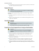
Removing the Faceplate To Remove a Faceplate with Feeder Cables Connected (Hot Install) Follow these steps to remove a faceplate with feeder cables already connected to the housing. 1 Remove all coax drop cables from the drop port F-connectors. 2 Using a 3/8-in. wrench, loosen all faceplate bolts. 3 If the housing is installed on a strand, go to step 4. If the housing is installed on a pedestal, go to step 5. WARNING: Protect yourself from electric shock and your equipment from damage.
Chapter 2 Installing the Tap Front View: Back View: Proceed to step 6. 6 Pull the faceplate straight out from the housing. You need to use a small amount of force to pull the faceplate out. CAUTION: Handle the faceplate with care to avoid damage to the circuitry mounted to the rear of the faceplate.
Installing the Tap Housing on a Strand Installing the Tap Housing on a Strand The strand-mounted configuration has the feeder cable entering one side of the unit and exiting the other side. The unit has one strand clamp with a strand clamp bolt and uses a standard cable strand for mounting. To Install the Tap Housing on a Strand Follow these steps to install a tap housing on a strand. 4014133 Rev D 1 Begin this procedure with the faceplate removed. Refer to To Remove the Faceplate (on page 16).
Chapter 2 Installing the Tap 5 Using a 3/16-in. hex-head driver or 3/16-in. straight blade screwdriver, loosen the two seizure screws inside the housing. 6 Thread the prepared KS-connectors into the housing at the cable side entry port locations as shown in the figure above. Make sure to tighten the connector according to the manufacturer’s recommended torque specification, typically 15 ft-lb to 25 ft-lb (20.3 Nm to 33.9 Nm), but not to exceed 60 ft-lb (81.3 Nm). 7 Using a 3/16-in.
Installing the Tap Housing in a Pedestal Installing the Tap Housing in a Pedestal The pedestal-mounted configuration has the feeder cable entering and exiting the unit from the bottom. The tap without traps or filters fits in a 6-in. round or square pedestal. A larger pedestal is needed if traps or filters are installed. To Install the Tap Housing in a Pedestal Follow these steps to install a tap housing in a pedestal. 4014133 Rev D 1 Begin this procedure with the faceplate removed.
Chapter 2 Installing the Tap 5 Using a 3/16-in. hex-head driver or 3/16-in. straight blade screwdriver, loosen the two seizure screws inside the housing. 6 Thread the prepared KS-connectors into the housing at the cable side entry port locations as shown in the figure above. Make sure to tighten the connector according to the manufacturer’s recommended torque specification, typically 15 ft-lb to 25 ft-lb (20.3 Nm to 33.9 Nm), but not to exceed 60 ft-lb (81.3 Nm). 7 Using a 3/16-in.
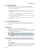
Mounting the Faceplate Mounting the Faceplate After mounting the housing and connecting the feeder cables, you are ready to install the faceplate in the tap housing. To Mount the Faceplate Follow these steps to attach the faceplate to the housing. 1 If the housing is installed on a strand, go to step 2. If the housing is installed in a pedestal, go to step 3. WARNING: Protect yourself from electric shock and your equipment from damage. Certain components can deliver an electrical shock.
Chapter 2 Installing the Tap Front View: Back View: Proceed to step 4. 24 4 Inspect the housing gasket and all mating surfaces. Wipe off any dirt, moisture, or debris. 5 Place the faceplate on the tap housing. Push firmly on the faceplate to seat it in the housing. 6 Remove the grounding wire assembly.
Mounting the Faceplate 7 4014133 Rev D Using a 3/8 in. wrench, tighten the faceplate bolts from 50 in-lb to 60 in-lb (5.6 Nm to 6.8 Nm).
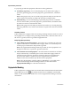
Chapter 2 Installing the Tap Installing Optional Modules The plug-in reverse attenuator module comes in values of 3, 6, 9, and 12 dB. The reverse attenuator is a plug-in module that can be installed in the field. Refer to Optional Modules (on page 8) for details. To Install the Reverse Attenuator Follow these steps to install the reverse attenuator. 26 1 If the faceplate is mounted in the tap housing, before proceeding, follow the steps in To Remove the Faceplate (on page 16).
Installing Optional Modules 4 Align the reverse attenuator pins with the five pin holes on the tap faceplate. Note: Be sure the reverse attenuator is seated securely on the socket. 5 4014133 Rev D Clean the decal area of any dirt or oil. Attach the appropriate decal shipped with the module.
3 Chapter 3 Customer Support Information If You Have Questions If you have technical questions, call Cisco Services for assistance. Follow the menu options to speak with a service engineer. Access your company's extranet site to view or order additional technical publications. For accessing instructions, contact the representative who handles your account. Check your extranet site often as the information is updated frequently.
Chapter 3 Customer Support Information 30 4014133 Rev D
A Appx auto letter Appendix A Technical Information This appendix contains important technical information about the tap. In This Appendix 4014133 Rev D Specifications ......................................................................................... 32 Tap Accessory Part Numbers..............................................................
Appendix A Technical Information Specifications The following are the specifications for the tap. Note: Specifications are subject to change without notice. 2/4-Way Tap Dimensions Item Specification Height 3.6 in. (91.44 mm) Width 3.6 in. (91.44 mm) Depth 3.0 in. (76.2 mm) 2/4/8-Way Tap Dimensions Item Specification Height 4.25 in. (107.95 mm) Width 5.25 in. (133.35 mm) Depth 3.0 in. (76.
Specifications AC/RF Bypass Switch Performance Item Specification System open circuit time 0 ms Contact resistance 10 m max Current and voltage capacity 15 A, 60 V AC to 90 V AC Frequency bandpass 5 MHz to 1000 MHz w/DC Standards Compliance 4014133 Rev D Standard Committee Standard SCTE F-port interface specification IPS-SP-400 FCC Part 76 EU EMC 50083-2 33
Appendix A Technical Information Tap Accessory Part Numbers The following tables list the accessories available for the tap. Part numbers for complete tap assemblies and tap faceplates are listed in the Flexible Solutions Taps Data Sheet, part number 7009943, which can be downloaded from the Cisco website. Reverse Attenuator Plug-ins Part Number Description Label Color 4013485 R.A. 3 dB, Reverse Attenuators-FST, 3 dB Red 4013486 R.A. 6 dB, Reverse Attenuators-FST, 6 dB Red 4013487 R.A.
Index 2 R 2/4/8-way Flexible Solutions Tap Full Profile Faceplate • 7 2/4/8-way Flexible Solutions Tap Full Profile Housing • 5 2/4/8-Way Tap Dimensions • 32 2/4-way Flexible Solutions Tap Standard Faceplate • 6 2/4-way Flexible Solutions Tap Standard Housing • 4 2/4-Way Tap Dimensions • 32 Removing the Faceplate • 16 Reverse Attenuator Plug-ins • 34 A AC/RF Bypass Switch Performance • 33 C Customer Support Information • 29 D Description of the Flexible Solutions Tap • 3 E S Specifications • 32 Stan
Cisco Systems, Inc. 5030 Sugarloaf Parkway, Box 465447 Lawrenceville, GA 30042 678 277-1120 800 722-2009 www.cisco.com This document includes various trademarks of Cisco Systems, Inc. Please see the Notices section of this document for a list of the Cisco Systems, Inc. trademarks used in this document. Product and service availability are subject to change without notice. © 2007, 2008, 2012 Cisco and/or its affiliates. All rights reserved.